ACM8 Series UL Listed Sub-Assembly Access Power Controllers Installation Guide Models Include: ACM8 - Eight (8) Fuse Protected Outputs ACM8CB - Eight (8) PTC Protected Outputs Rev. 042811 More than just power.
Overview: These units are UL Listed Sub-Assembly multi-output Access Power Controllers that convert one (1) 12 to 24 volt DC input into eight (8) independently controlled fused or PTC protected outputs. These power outputs can be converted to dry form “C” contacts (fused models only). Outputs are activated by an open collector sink or normally open [NO] dry trigger input from an Access Control System, Card Reader, Keypad, Push Button, PIR, etc.
Installation Instructions: Wiring methods shall be in accordance with the National Electrical Code/NFPA 70/NFPA 72/ANSI, and with all local codes and authorities having jurisdiction. Product is intended for indoor use only and should be installed by qualified personnel. 1. Refer to Sub Assembly Installation Instruction for mounting Rev. MS050913. Carefully review: Typical Application Diagram (pg. 4) Terminal Identification Table (pg. 5) LED Diagnostics (pg. 5) Hook-up Diagrams (pg. 6) 2.
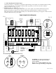
(c) FACP Signaling Circuit input trigger: Connect the positive (+) and negative (-) from the FACP signaling circuit output to the terminals marked [+ INP -]. Connect the FACP EOL to the terminals marked [+ RET -] (polarity is referenced in an alarm condition). Jumper J3 must be cut (Fig. 3, pg. 6). 6. FACP Dry form “C” output (Fig. 1a, pg.
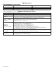
LED Diagnostics: ACM8 and ACM8CB Access Power Controller LED ON LED 1- LED 8 (Red) Output relay(s) energized. Trg (Green) FACP input triggered (alarm condition). OFF Output relay(s) de-energized. FACP normal (non-alarm condition). Terminal Identification Tables: ACM8 and ACM8CB Access Power Controller Terminal Legend Function/Description -- Power + 12VDC or 24VDC input from power supply board.
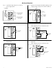
Hook-up Diagrams: Fig. 2 Optional hook-up using two (2) isolated power supply inputs: Fig. 3 Polarity reversal input from FACP signaling circuit output (polarity is referenced in alarm condition): CUT JUMPER J3 CUT JUMPERS J1 AND J2 J2 ISOLATED POWER INPUT 12 OR 24 VAC OR VDC (ACM8 POWER) J1 INTERFACE J3 TRG Fig. 4 Normally Open - Non-Latching FACP trigger input: J3 Fig. 5 Normally Open FACP Latching trigger input with reset: (This output has not been evaluated by UL) INTERFACE J3 TRG N.O.
Notes: ACM8/CB Sub-Assembly -7-
Notes: Altronix is not responsible for any typographical errors. 140 58th Street, Brooklyn, New York 11220 USA, 718-567-8181, fax: 718-567-9056 web site: www.altronix.com, e-mail: info@altronix.com, Lifetime Warranty, Made in U.S.A.