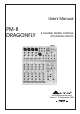
User's Manual PM-8 DRAGONFLY 8-CHANNEL MIXING CONSOLE WITH DIGITAL EFFECTS R LTO www.altoproaudio.com Version 1.
Fuse SAFETY RELATED SYMBOLS To prevent fire and damage to the product, use only the recommended fuse type as indicated in this manual. Do not short-circuit the fuse holder. Before replacing the fuse, make sure that the product is OFF and disconnected from the AC outlet. CAUTION RISK OF ELECTRIC SHOCK DO NOT OPEN This symbol, wherever used, alerts you to the presence of un-insulated and dangerous voltages within the product enclosure.
PREFACE Dear Customer: Thanks for choosing LTO PM-8 DRAGONFLY 8-Channel Mixing Console With Digital Effects ,which is the results of LTO AUDIO TEAM's work and researches. For the LTO AUDIO TEAM, music and audio are more than a profession, it is a passion and an obsession! We have, in fact, been designing professional audio products for a number of years in cooperation with many of the world's major brands. The LTO line represents unparalleled analogue and digital products made by musicians, for musicians.
TABLE OF CONTENTS 1. INTRODUCTION..................................................................................................................................................4 2. FEATURES..........................................................................................................................................................5 3. READY TO START...............................................................................................................................................
1. INTRODUCTION Thank you very much for expressing your confidence in LTO products by purchasing LTO PM-8 DRAGONFLY 8Channel Mixing Console with Digital Effects. The PM-8 DRAGONFLY 8-Channel Mixing Console with Digital Effects is a professional compact mixer, which provides the state of the art digital amplifier technology specifically. You will get the smooth, accurate more natural and open sound from this apparatus, And it is really ideal for small gigs, recording and fixed PA installations.
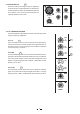
2. FEATURES The PM-8 DRAGONFLY 8-Channel Mixing Console with Digital Effects is designed for professional appliance.
3. READY TO START 3.1 There is a small black box provided with your PM-8 DRAGONFLY. This is the specific power supply box. Connect the proper terminal into your PM-8 DRAGONFLY and the power supply box into an AC socket. 3.2 Be sure that the main power switch is turned off before connecting the Mixer to the power supply box. Also, you should make sure that all Input and Output Controls are turned down. This will avoid damages to your speakers and avoid excessive noise. 3.
4.
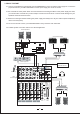
4.1 The MONO MIC/LINE channels 1 These are Channel 1 through Channel 4. You can connect a balanced, low impedance microphone to the XLR socket. On the 1/4" phone jack you can connect either a microphone or a line level instrument. You shall never connect an unbalanced microphone to the XLR socket if you do not want to damage both the Microphone and the Mixer, when Phantom power is switched on. 18 Volt phantom power MIC 1 2 1 3 5 1 It is available only to the XLR Mic sockets.
6 4.5 STEREO INPUTS These are Channel 5 through 8. They are organised in stereo pair and are provided with 1/4" TRS phone sockets (Channel 5-6 also provid with Mic input and Trim control). If you connect only the left jack, the input will operate in mono mode. 2 LINE IN 5/6 LINE IN 7/8 LEFT (MONO) LEFT (MONO) RIGHT RIGHT 1 3 6 MIC (MONO) TRIM 0dB 44dB MIC 4.6 The 3 BANDS EQUALISER A 3-band equaliser is provided for all input channels with a wide range of frequency adjustment. 4.6.
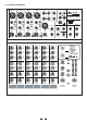
10 4.7 AUX SEND These two controls are used to adjust the level of the signal sent to AUX buses, and their adjustable range goes from to +15dB. 0 EQ AUX1 is configured as PRE-FADER, so, generally, it can be used for monitor application. HI 12kHz -15 While AUX2 is configured as POST-FADER, therefore, most of the times, it will be used for effects and processors input, however, you can also change it to PRE-FADER configuration according to the specific application.
4.11 MASTER SECTION 14 - MAIN MIX LEVEL This Control sets the amount of signal sent either to the Main Out socket or to the Tape Output. - LED METER 15 This stereo 12 segments Led Meter will indicate the level of the overall output signal. - 2 TRACK signal path 16 If you push down the 2TK TO CONTROL ROOM button, the 2 TRACK IN signal will be routed into the Control Room output and the level will be adjusted by the Control Room knob nearby the Main MIX LEVEL knob.
- 24 BIT DIGITAL EFFECTS PRESETS 22 Adjust this knob to select the right effect you wish to perform. There are total 16 options for you: several kinds of reverb, mono and stereo delay, effects with modulation, and versatile two-effect combination. 23 23 VARIATIONS 22 Since you have selected the preferable effect, the next step, please go with the fine consideration, there are also total 16 variations for each preset, each variation may be managed by several different factors.
30 - 2-TRACK IN/OUT Input Use the Tape input if you wish to listen to your Mix from a Tape Recorder or DAT, you can assign the signal coming from the Tape Recorder either to a pair of studio monitor using the Control Room assignment on the front panel or directly to the Main Mix. Output These 1/4" TRS sockets will route the main mix into a tape recorder. POWER AMP 32 OFF 31 - 2TK IN This control is used to adjust the level of 2TK IN. ON C.
4.13 The Power Supply Box - AC Inlet 38 42 39 38 This is AC Inlet for connecting the AC power supply to the PM-8 power supply box. - Fuse Holder 39 ON The fuse is to prevent fire and damage to the product, Do not .short-circuit the fuse holder. Before replacing the fuse, make sure that the PM-8 power supply is disconnected from the AC inlet. Use only the recommended fuse type as indicated. - POWER Switch AC USA/Canada 100-120V~60Hz Fuse:T10A POWER ON POWER UK/Aust 240V~50Hz Fuse:T6.
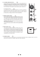
5.1 SOME FINAL TIPS ON WIRING CONFIGURATION You can connect unbalanced equipment to balanced inputs and outputs. Simply follow these schematics.
Ring=Return Signal (Connected together) To Channel Insert Sleeve=Ground/Screen Tip=Signal To Tape or FX Input Sleeve=Ground/Screen 'Tapped' Connection Direct Output Lead (Enables the Insert to be used as a Direct Output while maintaining the channel signal flow) To Processor Input Sleeve=Ground/Screen Tip=Send Signal Tip To Channel Insert Sleeve Ring Ring=Return Signal To Processor Output -Stereo lead for insert Connection (To be used when the processor does not employ a single jack connectio
6. FOR THE EXPERTS WHO WANTS TO KNOW MORE As we have told you previously in this Manual, the Aux Send 2 Control both on Mono and on stereo channels is factory wired as POST-FADER. If you have some skill in electronic components soldering you can modify this setting and have all your AUX sends configured as PRE-FADER.
7. PRESET LIST No. Preset Description Controllable parameter Parameter Variable range 1 VOCAL 1 Simulate a room with small delay time. Decay time Pre-delay 0.8~1.1s 0~79ms 2 VOCAL 2 Simulate a small space with slight decay time. Decay time Pre-delay 0.8~2.5s 0~79ms 3 LARGE HALL Simulate a large acoustic space of the sound. Decay time Pre-delay 3.6~5.4s 23~55ms 4 SMALL HALL Simulate a small acoustic space of the sound. Decay time Pre-delay 1.0~2.
8.
9.
Physical Dimension (W D H) Net weight(with power supply) Gross weight 21 290mm 250mm 100mm (11.41" 9.84" 3.93") 5.6Kg (12.35lb) 6.2 Kg (13.
10. WARRANTY 1. WARRANTY REGISTRATION CARD To obtain Warranty Service, the buyer should first fill out and return the enclosed Warranty Registration Card within 10 days of the Purchase Date. All the information presented in this Warranty Registration Card gives the manufacturer a better understanding of the sales status, so as to purport a more effective and efficient after-sales warranty service.
SEIKAKU TECHNICAL GROUP LIMITED No. 1, Lane 17, Sec. 2, Han Shi West Road, Taichung 40151, Taiwan http://www.altoproaudio.com Tel: 886-4-22313737 email: alto@altoproaudio.com Fax: 886-4-22346757 All rights reserved to ALTO. All features and content might be changed without prior notice. Any photocopy, translation, or reproduction of part of this manual without written permission is forbidden. Copyright c 2005 SEIKAKU GROUP NF02048-1.