User's Manual PM-12 DRAGONFLY 12-CHANNEL MIXING CONSOLE WITH DIGITAL EFFECTS R LTO www.altoproaudio.com Version 1.
the recommended fuse type as indicated in this manual. Do not short-circuit the fuse holder. Before replacing the fuse, make sure that the product is OFF and disconnected from the AC outlet. SAFETY RELATED SYMBOLS CAUTION RISK OF ELECTRIC SHOCK DO NOT OPEN Protective Ground This symbol, wherever used, alerts you to the presence of un-insulated and dangerous voltages within the product enclosure. These are voltages that may be sufficient to constitute the risk of electric shock or death.
PREFACE Dear Customer: Thank you for choosing the LTO PM-12 Dragonfly 12-Channel Mixing Console with Digital Effects, which is the result of our LTO AUDIO TEAM's endeavours. For the LTO AUDIO TEAM, music and audio are more than a profession, it is a passion and an obsession! We have, in fact, been designing professional audio products for a number of years in cooperation with many of the world's major brands.
TABLE OF CONTENTS 1. INTRODUCTION...................................................................................................................................................4 2. FEATURES...........................................................................................................................................................5 3. QUICK START....................................................................................................................................................
1. INTRODUCTION Thank you very much for expressing your confidence in LTO products by purchasing LTO PM-12 Dragonfly 12Channel Mixing Console with Digital Effects. The PM-12 is professional compact mixer, which provides the state of the art switching power and advanced digital amplifier technology specifically. You will get the smooth, accurate more natural and open sound from this apparatus, it is really ideal for large gigs, recording and fixed PA in-stallations.
2. FEATURES The PM-12 Dragonfly 12-Channel Mixing Console with Digital Effects is designed for professional application.
3. QUICK START 3.1 Please check the AC Voltage available in your country before connecting your PM-12 to the AC socket. 3.2 Be sure that the main power switch is turned off before connecting the Mixer to the AC socket. Also, you should make sure that all Input and output controls are turned down. This will avoid damages to your speakers and avoid excessive noise. 3.
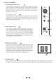
Stage Monitors Amplifier L R REPLACE WITH THE SAME TYPE FUSE AND RATING DISCONNECT SUPPLY CORD BEFORE CHANGING FUSE 4 OHM SPEAKER LOAD MIN. 300 WATTS/CH CAUTION: LOC AC INPUT RISK OF ELECTRIC SHOCK DO NOT OPEN Apparaten skall anslutas till jordat uttag nar den ansluts till ett natverk OFF K WARNING: SHOCK HAZARD - DO NOT OPEN AVIS: RISQUE DE CHOC ELECTRIQUE - NE PAS OUVRIR K EUROPE 210-240V 50-60Hz Fuse: T6.
4.
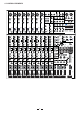
4. CONTROL ELEMENTS 1 4.1 The MONO MIC/LINE Channels These are channel 1 through channel 8. You can connect balanced, low impedance microphones to the XLR socket. On the 1/4" phone jack you can connect either a microphone or a line level instrument. You shall never connect an unbalanced microphone to the XLR socket if you do not want to damage both the microphone and the mixer. MIC 1 2 1 3 1 48 Volt phantom power LINE IN 1 2 It is available only to the XLR Mic sockets.
6 4.5 STEREO INPUTS These are Channel 9 through 12. They are organised in stereo pair and provided with 1/4" TRS phone sockets. If you connect only the left jack, the input will operate in mono mode. 4.6 +4dBu/-10dBV Switch LINE IN 9/10 LINE IN 11/12 LEFT (MONO) LEFT (MONO) 6 7 Your PM-12 provides the gain select switch, which is used to adjust the sensitivity of line input on stereo channels.
11 4.7.4 MID-LOW This control gives you up to 15dB boost or cut at 500Hz. 4.7.5 LOW 12 0 0 EQ EQ HI 12kHz This is the Bass control. Boost male voice or kickdrum and bass guitar. Your system will sound much bigger than what it is. The gain range goes from -15dB to +15dB and the center frequency is 80 Hz.
4.12 FADER 17 This fader will adjust the overall level of this channel and set the amount of signal sent to the main output or the corresponding subgroup output. SG/PEAK SG/PEAK MUTE 18 4.13 ASSIGNMENT Switches MUTE 10 10 dB dB 5 Each channel provides three assignment switches: SUB1-2, SUB 3-4 and MAIN L-R.
4.16 Master AUX SENDS Section 23 - 8 The four switches are used to determine the master AUX SEND levels, which can be varied from - to +15dB. - 0 23 +15 +15 8 2 When the external effect unit connected to mixer has no input gain control, you can get a further +15dB gain available form these AUX SEND controls.
4.18 SUBGROUPS Control Section - SUBGROUPS ASSIGN TO MAIN MIX 30 Through these switches, you can operate the subgroup faders as a master control for assigning the subgroups to MAIN MIX. Engage the LEFT switch to send the corresponding subgroup signal to MAIN MIX L, and the RIGHT switch for MAIN MIX R. When engaging the both switches, the signal will be sent to L/R of MAIN MIX.
4.22 24-BIT DIGITAL STEREO EFFECTS PROCESSOR 36 - PRESETS Control 0 8 AUX1 - +15 15 14 13 12 11 AUX2 37 - VARIATIONS Control 37 36 Adjust this knob to select the right effect you wish to perform. There are total 16 options for you: several kinds of reverb, mono and stereo delay, effects with modulation, and versatile two-effect combination.
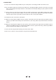
4.24 AUX SENDS Connectors 45 These 1/4" phone sockets are used to send out the signal from the AUX bus to external devices such as effects. 1 2 3 4 2 3 4 45 AUX SENDS 1 46 4.25 AUX RETURNS Connectors Use these stereo 1/4" phone sockets to return the sound of an effect unit to the main mix. You can also use them as the extra auxiliary inputs. 46 L L L L R R R R AUX RETUENS 4.
B LAMP - DFX OUT 51 4.30 DFX OUT FOOT SWITCH PHONES 12V 0.5A 52 53 54 MONO OUTPUT +15 LEVEL 8 A 55 56 51 This 1/4" socket is used to output the effect signal that comes from internal DSP module. 52 4.31 FOOTSWITCH This 1/4" socket can be used to connect an external footswitch to turn on/off the onboard effect module. 53 4.32 PHONES These sockets will send out the monitor signal to a pair of headphones. 4.
59 4.38 MAIN INSERT These two 1/4" phone sockets are stereo insert points and used to connect processors such as compressors, Expander etc.. When insert a external processor into the jack, the Main stereo signal will be taken out after the EQ and returned into the MAIN MIX output before the main mix fader. 4.
62 - Speaker Output Jacks CAUTTION LETHAL VOLTAGES MAY APPEAR AT OUTPUT TERMINALS CLASS 1 WIRING IS REOUIRED CHANNEL R SLEEVE PIN TIP CHANNEL L 2- 1- 1+ 2+ PIN 2- 1- 1+ 2+ SLEEVE TIP LOC LOC K K 4 OHM SPEAKER LOAD MIN. 300 WATTS/CH 62 Your PM-12 is equipped with the advanced class D audio amplifier and the state of the art switching power technology, which can provide wide operating voltage range, high output power and thermally protected functions etc..
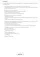
5. INSTALLATION AND CONNECTION Ok, you have got to this point and you are now in the position to successfully operate your PM-12. However, we advise you to read carefully the following section to be the real Master of your own mix. Not paying attention enough to the input signal level, to the routing of the signal and the assignment of the signal will result in unwanted distortion, a corrupted signal or no sound at all.
5.1 SOME FINAL TIPS ON WIRING CONFIGURATION You can connect unbalanced equipment to balanced inputs and outputs. Simply follow these schematics.
Ring=Return Signal (Connected together) To Channel Insert Sleeve=Ground/Screen Tip=Signal To Tape or FX Input Sleeve=Ground/Screen 'Tapped' Connection Direct Output Lead (Enables the Insert to be used as a Direct Output while maintaining the channel signal flow) To Processor Input Sleeve=Ground/Screen Tip=Send Signal Tip To Channel Insert Sleeve Ring=Return Signal Ring To Processor Output -Stereo lead for insert Connection (To be used when the processor does not employ a single jack connection
6. PRESET LIST 01. VOCAL1 No 1 2 3 4 5 6 7 8 9 10 11 12 13 14 15 16 Pre-delay 84 30 0 55 10 79 45 45 25 0 45 114 40 50 45 55 Rev Time 1.00 1.00 4.50 3.60 1.20 3.60 0.8 1.50 2.40 0.90 1.50 1.00 1.00 2.10 4.50 1.70 Room Size 39 8 10 11 9 8 41 41 9 41 10 45 9 10 11 Rev.
9 10 11 12 13 14 15 16 50 50 27 27 45 45 23 23 4.00 4.00 4.00 4.00 3.60 3.60 3.60 3.60 42 42 32 32 41 41 30 30 -0.96 -12.00 -0.96 -12.00 -0.96 -12.00 -0.96 -12.00 82 82 82 82 88 88 88 88 Pre-delay 45 45 23 23 40 40 20 20 40 40 20 20 40 40 20 20 Rev Time 2.90 2.90 2.90 2.90 2.10 2.10 2.10 2.10 1.50 1.50 1.50 1.50 1.00 1.00 1.00 1.00 Room Size 39 39 28 28 38 38 27 27 37 37 26 26 36 36 25 25 Hi Damp -0.96 -12.00 -0.96 -12.00 -0.96 -12.00 -0.96 -12.00 -0.96 -12.00 -0.96 -12.00 -0.96 -12.00 -0.96 -12.
06. SMALL ROOM No 1 2 3 4 5 6 7 8 9 10 11 12 13 14 15 16 Pre-delay 45 45 23 23 40 40 20 20 40 40 20 20 40 40 20 20 Rev Time 2.10 2.10 2.10 2.10 1.50 1.50 1.50 1.50 1.00 1.00 1.00 1.00 0.70 0.70 0.70 0.70 Room Size 17 17 9 9 17 17 9 9 16 16 8 8 16 16 8 8 Hi Damp -0.96 -12.00 -0.96 -12.00 -0.96 -12.00 -0.96 -12.00 -0.96 -12.00 -0.96 -12.00 -0.96 -12.00 -0.96 -12.00 Pre-delay 10 10 10 10 10 10 10 10 10 10 10 10 10 10 10 10 Rev Time 6.10 5.40 4.50 4.00 3.60 2.90 2.40 2.10 1.70 1.50 1.30 1.20 1.00 0.80 0.
9 10 11 12 13 14 15 16 0 0 0 0 0 0 0 0 3.60 3.60 2.90 2.90 2.10 2.10 1.30 1.30 23 23 23 23 21 21 21 21 -0.96 -12.00 -0.96 -12.00 -0.96 -12.00 -0.96 -12.00 92 92 92 92 100 100 100 100 Pre-delay 35 35 30 30 30 30 30 84 0 0 0 0 0 0 0 0 Rev Time 5.4 5.4 4.50 4.50 4 4 3.60 3.60 2.90 2.90 2.40 2.40 1.70 1.70 1.30 1.30 Room Size 35 35 33 33 30 30 28 28 22 22 22 22 22 22 22 22 Hi Damp -0.96 -12.00 -0.96 -12.00 -0.96 -12.00 -0.96 -12.00 -0.96 -12.00 -0.96 -12.00 -0.96 -12.00 -0.96 -12.
11. STEREO DELAY No 1 2 3 4 5 6 7 8 9 10 11 12 13 14 15 16 Delay 400 375 352 326 312 300 288 277 267 258 250 241 238 230 222 214 Right Delay 200 187 176 163 156 150 144 138 133 129 125 120 119 115 111 107 Left F.B. 51 51 40 40 40 40 40 40 30 38 37 36 36 37 38 37 Right F.B. 72 72 72 72 72 72 66 66 66 73 73 73 73 74 73 73 Mod. Freq 2.79 2.52 2.33 2.25 2.10 1.99 1.75 1.61 1.34 1.22 1.00 0.80 0.65 0.54 0.42 0.16 Pitch. Depth 30 40 40 40 40 40 40 50 50 70 70 70 70 70 70 70 Left F.B.
2.33 1.99 1.70 1.35 1.00 0.50 11 12 13 14 15 16 40 40 40 40 70 70 -3(0) -3(0) -3(0) -2(0) -2(0) -2(0) 14. REVERB+DELAY No 1 2 3 4 5 6 7 8 9 10 11 12 13 14 15 16 Rev Time 2.90 2.90 2.90 2.90 2.40 2.40 2.40 2.40 2.10 2.10 1.50 1.50 1.50 1.50 1.00 1.00 Room Size 39 39 39 39 39 39 39 39 26 26 26 26 26 26 26 26 Left Delay 375 326 300 277 258 241 230 211 375 326 300 277 258 241 230 211 Right Delay 187 163 150 138 129 120 115 107 187 163 150 138 129 120 115 107 Left F.B.
16. REVERB+CHORUS No 1 2 3 4 5 6 7 8 9 10 11 12 13 14 15 16 Rev Time 2.90 2.90 2.90 2.90 2.90 2.90 2.90 2.90 1.50 1.50 1.50 1.50 1.50 1.50 1.00 1.00 Room Size 39 39 39 39 39 39 39 39 26 26 26 26 26 26 26 26 Mod. Freq. 4.74 4.12 3.67 3.02 2.63 1.99 1.35 0.50 4.74 4.12 3.67 3.02 2.63 1.99 1.35 0.50 29 Pitch. Depth 40 40 40 40 40 40 70 70 40 40 40 40 40 40 70 70 Left F.B.
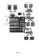
30 A B C D 1 2 3 1 5e S 3c R 4d RN 2b TN 1a T 5e S - + - + DFX OUT RIGHT LEFT(MONO) R T S STEREO AUX RTN4 RIGHT LEFT(MONO) STEREO AUX RTN3 RIGHT LEFT(MONO) STEREO AUX RTN2 RIGHT LEFT(MONO) STEREO AUX RTN1 5e S 3c R 4d RN 2b TN 1a T 5e S 3c R 4d RN 2b TN 1a T 5e S 3c R 4d RN 2b TN 1a T 5e S 3c R 4d RN 2b TN 1a T 5e S 3c R 4d RN 2b TN 1a T 5e S 3c R 4d RN 2b TN 1a T 5e S 3c R 4d RN 2b TN 1a T 5e S 3c R 4d RN 2b TN 1a T 2 MUTE VARIATIONS PRESETS FX OUT R FX OUT
8. TECHNICAL SPECIFICATION Mono input channels Microphone input Frequency response Distortion (THD & N) Gain range SNR (Signal to Noise Ratio) Line input Frequency response Distortion (THD & N) Sensitivity range electronically balanced, discrete input configuration 10Hz to 55kHz, + 3dB 0.005% at + 4dBu, 1kHz 0dB to 45dB (MIC) Line input Frequency response Distortion (THD & N) Balanced/unbalanced 10Hz to 55kHz, + 3dB 0.
Power AMP section Power AMP output (sine @ 1% THD) 300W into 4ohm Main voltage USA/Canada Europe Power supply 100 120V~, 60Hz 210 240V~, 50Hz U.K./Australia 240V~, 50Hz 650 watts 100 120V~ : T10AL 210 240V~ : T6.3AL Standard IEC receptacle Power Consumption Fuse Main connection Physical Dimension (W D H) 608/589mm 524/471mm 120/30mm (17.55"/17.0" 15.13"/13.60" 3.47"/0.96") 6.15Kg (13.46lb) 7.6Kg (16.
9. WARRANTY 1. WARRANTY REGISTRATION CARD To obtain Warranty Service, the buyer should first fill out and return the enclosed Warranty Registration Card within 10 days of the Purchase Date. All the information presented in this Warranty Registration Card gives the manufacturer a better understanding of the sales status, so as to purport a more effective and efficient after-sales warranty service.
SEIKAKU TECHNICAL GROUP LIMITED No. 1, Lane 17, Sec. 2, Han Shi W. Road, Taichung, 401 Taiwan http://www.altomobile.com Tel: 886-4-22313737 email: info@altomobile.com Fax: 886-4-22346757 All rights reserved to ALTO Mobile. Due to continued development in response to customer feedback, product features, specifications and/or internal/external design may be changed without prior notice. No photocopying, translation or reproduction of any part of this user manual is allowed without prior written permission.