R LTO OWNER'S MANUAL MAC 2.2/2.3/2.4 PROFESSIONAL STEREO AMPLIFIERS www.altoproaudio.com Version 1.
IMPORTANT SAFETY INSTRUCTION CAUTION RISK OF ELECTRIC SHOCK DO NOT OPEN TO REDUCE THE RISK OF ELECTRIC SHOCK PLEASE DO NOT REMOVE THE COVER OR THE BACK PANEL OF THIS EQUIPMENT. THERE ARE NO PARTS NEEDED BY USER INSIDE THE EQUIPMENT. FOR SERVICE, PLEASE CONTACT QUALIFIED SERVICE CENTERS. WARNING To reduce the risk of electric shock and fire, do not expose this equipment to moisture or rain. Dispose of this product should not be placed in municipal waste and should be separate collection. 11.
IN THIS MANUAL: 1. INTRODUCTION..............................................................................1 2. FEATURES.....................................................................................1 3. CONTROL ELEMENTS...................................................................5 4. OPERATION...................................................................................8 5. BLOCK DIAGRAM........................................................................11 6.
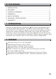
SP OT L IG HT R LTO MAC 2.2 ON Stereo Power Amplifier CH1 CH2 POWER PROT CLIP SIG OFF POWER MAC 2.2 R LTO MAC 2.3 ON Stereo Power Amplifier CH1 CH2 POWER PROT CLIP SIG OFF POWER MAC 2.3 R LTO MAC 2.4 ON Stereo Power Amplifier CH1 POWER CH2 PROT CLIP SIG OFF POWER MAC 2.
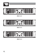
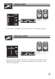
HOOK STEREO MODE UP R LTO MAC 2.4 ON Stereo Power Amplifier CH1 CH2 POWER PROT CLIP SIG OFF POWER In this mode, 2 independent channels are sent to 2 separate speakers. HOOK PARALLEL MODE UP R LTO MAC 2.4 ON Stereo Power Amplifier CH1 POWER CH2 PROT CLIP SIG OFF POWER One mono signal is input to channel 1 or Channel 2 of the MAC 2 series amplifier and then output to 2 separate speakers. Each speaker volume can be set separately.
HOOK BRIDGE MODE UP R LTO MAC 2.4 Stereo Power Amplifier ON CH1 POWER CH2 PROT CLIP SIG OFF POWER The stereo or mono signal input to channel 1 and channel 2 is combined on the BRIDGE MONO connector. Only channel 1 Gain control is active. The power at the output will be combined power of the two channels. HOOK STEREO BIAMP UP R LTO MAC 2.4 ON Stereo Power Amplifier CH1 CH2 POWER PROT CLIP SIG OFF POWER R LTO MAC 2.
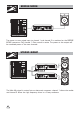
SP OT L IG 3. CONTROL ELEMENTS HT Front Panel: 1 POWER SWITCH It powers the MAC 2 series ON and OFF. 2 POWER INDICATOR LED This Power LED lights up when the unit is powered up. 3 PROTECTION LED a. It will light up when the unit is in Protection Mode due to overheating, short circuit, low impedance load or other causes (For MAC 2.2 & MAC 2.3). b. It will light up when the unit is in Protection Mode due to overheating, exist DC output or other causes (Only for MAC 2.4 ). 4 Clip LED a.
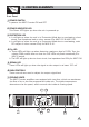
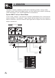
SP OT L IG 3. CONTROL ELEMENTS HT Rear Panel: 8 CIRCUIT BREAKER This is an electronic fuse for protecting the unit from possible damage. When the unit is overloaded or the temperature inside the unit is too high, this push-type button will spring out and disconnect the power supply. Push the Breaker to restore normal working conditions. 9 IEC socket for AC power cable Connect the supplied main cord.
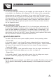
SP OT L IG 3. CONTROL ELEMENTS HT 13 CLIP-LIMITER SWITCH If a very high level signal is driven into the amplifier, the output signal will "CLIP", that is the peaks of the waveform will be flattered. The Clip Limiter circuit automatically reduces the gain to prevent the overdrive. You can switch the Clip Limiter circuit ON and OFF via the (13) switch on the rear panel of your MAC 2 series.
4. OPERATION The MAC 2 series amplifiers provide three operating modes: stereo mode, parallel (mono) mode and bridged mode, you can decide each specific operating mode according to your actual application circumstance. Operate MAC 2 series in Stereo Mode In this mode, channel 1 and channel 2 operate independently (as a conventional stereo amplifier).
4. OPERATION Operate MAC 2 series in Parallel Mode In this mode, the channel 1 input signal will be output from the output connectors of both channels. The channel 2 input jack is not used; the channel 1 and channel 2 volumes can be adjusted independently. Use the Parallel Mode when you want to drive two speakers with only one input signal keeping separate control of the volume of the two channels.
4. OPERATION Operate MAC 2 series in Bridged Mode In this mode, the channel 1 input signal will be output from the bridge output connectors. ( The 2 RED binding post ) In this case, use the channel 1 volume control to adjust the volume, keep the volume control of channel 2 turned completely down ( counter clockwise ). Bridged mode is intended for driving loads with a total impedance of 4 ohms or greater. In Bridge Mode you will combine the power of both channels into one speaker.
5.
6. TECHNICAL SPECIFICATIONS MAC 2.2 MAC 2.3 MAC 2.4 1000 W 1800 W 8 Ohms (RMS) x2 350 W x 2 230 W x 2 8 Ohms (RMS) 710 W 1000 W 1800 W 4 Ohms (EIAJ) 1500 W 2200 W 3100 W POWER SPECIFICATIONS Stereo Mode (Both channels driven) 20Hz~20KHz Bridge Mono Mode 20Hz~20kHz 750 W 2 Ohms (EIAJ) 4 Ohms (RMS) 900 W 510 W 560 W 285 W ELECTRICAL SPECIFICATIONS 1.15 V (+3.4 dBu) INPUT SENSITIVITY 1.15 V (+3.
7. WARRANTY 1. WARRANTY REGISTRATION CARD To obtain Warranty Service, the buyer should first fill out and return the enclosed Warranty Registration Card within 10 days of the Purchase Date. All the information presented in this Warranty Registration Card gives the manufacturer a better understanding of the sales status, so as to provide a more effective and efficient after-sales warranty service.
SEIKAKU TECHNICAL GROUP LIMITED NO. 1, Lane 17, Sec. 2, Han Shi West Road, Taichung 40151, Taiwan http://www.altoproaudio.com Tel: 886-4-22313737 email: alto@altoproaudio.com Fax: 886-4-22346757 All rights reserved to ALTO. All features and content might be changed without prior notice. Any photocopy, translation, or reproduction of part of this manual without written permission is forbidden. Copyright c 2007 Seikaku Group NF03010-1.