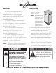
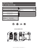
GAS FRYER FryTech Series ASF-60G shown with optional automatic basket lifts ASF-60G and ASF-75G Gas Fryers with Deluxe Control • INSTALLATION ASF-75G shown with optional automatic basket lifts • OPERATION • MAINTENANCE W164 N9221 Water Street • P.O. Box 450 • Menomonee Falls, Wisconsin 53052-0450 USA PHONE: 262.251.3800 • 800.558.8744 USA / CANADA FAX: 262.251.7067 • 800.329.8744 U . S . A . www.alto-shaam.com printed in u.s.a.
Delivery Unpacking Safety Procedures and Precautions 1 1 2 Installation Installation Requirements Dimension Drawings, weights & capacities Clearance Requirements Site Installation & Leveling Ventilation Gas Specifications Gas Connection Restraint Requirements - Mobile Equipment Electrical Specifications 3-11 3-4 5 6 7 8 9 10 11 Operating Instructions Oil/Shortening Requirements Controls Behind Access Panel Boil-Out Instructions Start-Up & General Operation Oil Filtration (For units with installed option
DELIVERY UNPACKING This Alto-Shaam appliance has been thoroughly tested and inspected to ensure only the highest quality unit is provided. Upon receipt, check for any possible shipping damage and report it at once to the delivering carrier. See Transportation Damage and Claims section located in this manual. This appliance, complete with unattached items and accessories, may have been delivered in one or more packages.
INSTALLATION SAFETY PROCEDURES AND PRECAUTIONS Knowledge of proper procedures is essential to the safe operation of electrically and/or gas energized equipment. In accordance with generally accepted product safety labeling guidelines for potential hazards, the following signal words and symbols may be used throughout this manual. DANGER Used to indicate the presence of a hazard that WILL cause severe personal injury, death, or substantial property damage if the warning included with this symbol is ignored.
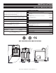
INSTALLATION ASF-75G SPECIFICATIONS DIMENSIONS exterior (h x w x d) ASF-75G without filtration or lifts 44-13/16” x 24-13/16” x 37-7/16” (1138mm x 629mm x 951mm) ASF-75G with filtration and lifts 44-13/16” x 24-13/16” x 38-11/16 (1138mm x 629mm x 983mm) basket dimensions (h x w x d) 6” x 9-3/16” x 14-3/16” (152mm x 232mm x 337mm) STANDARD ACCESSORIES Basket, Half-Size (2 included as standard) BS-27140 Brush Set (one 3-brush set included as standard) scrub brush BH-28693 straight brush BH-28691 Filter, Pa
INSTALLATION ASF-60G SPECIFICATIONS DIMENSIONS exterior (h x w x d) 44-3/4” x 15-3/4” x 33-5/8” (1136mm x 400mm x 853mm) basket dimensions (h x w x d) 5-3/16” x 5-7/8” x 13-13/16” (131mm x 149mm x 328mm) C APA CI T Y SHORTENING/OIL: STANDARD ACCESSORIES Basket, Half-Size (2 included as standard) BS-27963 Brush Set (one 3-brush set included as standard) scrub brush BH-28693 straight brush BH-28691 OPTIONS 62 lb (28 kg) maximum Fry Pot Cover LOAD CAPACITY: 8 lb (4 kg) 5007596 Strainer/Skimmer maximu
INSTALLATION DANGER DANGER IMPROPER INSTALLATION, ALTERATION, ADJUSTMENT, SERVICE, OR MAINTENANCE COULD RESULT IN SEVERE INJURY, DEATH, OR CAUSE PROPERTY DAMAGE. READ THE INSTALLATION, OPERATING AND MAINTENANCE INSTRUCTIONS THOROUGHLY BEFORE INSTALLING OR SERVICING THIS EQUIPMENT. AVERTISSEMENT : UNE INSTALLATION, UN AJUSTEMENT, UNE ALTÉRATION, UN SERVICE OU UN ENTRETIEN NON CONFORME AUX NORMES PEUT CAUSER DES DOMMAGES À LA PROPRIÉTÉ, DES BLESSURES OU LA MORT.
INSTALLATION SITE INSTALLATION 1. It is the responsibility of the installer to verify that this fryer installation is in compliance with the specifications listed in this manual and with local code requirements. 9. 2. Hood installation is required. 10. 3. Both cooking and cleaning functions require unobstructed access. The frypot, control panel, and front access door must be maintained free from obstruction. The access door must be accessible for service and maintenance. 4.
INSTALLATION VENTILATION DANGER WARNING This appliance shall be installed in conformity with the current regulations and used only in a well ventilated location. Consult the instructions before installing and using this appliance. Installation, air adjustment and/or service work must be in accordance with all local codes and must be performed by a certified service technician qualified to work on gas appliances. An adequate ventilation system is required for commercial cooking equipment.
INSTALLATION GAS SPECIFICATIONS The Alto-Shaam open gas fryer has been set to operate with either natural gas or propane as indicated on the fryer identification name plate. DANGER CONNECTING TO THE WRONG GAS SUPPLY COULD RESULT IN FIRE OR AN EXPLOSION CAUSING SEVERE INJURY AND PROPERTY DAMAGE. The appliance and its individual shutoff valve must be disconnected from the gas supply piping system during any pressure testing of that system at test pressures in excess of 1/2 psi.
INSTALLATION GAS CONNECTION DANGER Installation, air adjustment and/or service work must be in accordance with all local codes and must be performed by a certified service technician qualified to work on gas appliances. Use an approved INCORRECT CORRECT gas pipe sealant at all external threaded connections, gas piping used on gas connections must avoid sharp bends that may restrict the flow of gas to the appliance. If the connected pressure exceeds 14.0” W.C. (3.
INSTALLATION RESTRAINT REQUIREMENTS - MOBILE EQUIPMENT The fryer must be supplied with a connector that complies with all state and local installation codes. Any appliance that is not furnished with a power supply cord but that includes a set of casters must be tethered. Adequate means must be provided to limit the movement of this appliance without depending on or transmitting stress to the electrical conduit. The following requirements apply: 1. Casters must be a maximum height of 4-inches (102mm). 2.
INSTALLATION ELECTRICAL REQUIREMENTS DANGER To avoid electrical shock, this appliance MUST be adequately grounded in accordance with local electrical codes or, in the absence of local codes, with the current edition of the National Electrical Code ANSI/ NFPA No. 70. In Canada, all electrical connections are to be made in accordance with CSA C22.1, Canadian Electrical Code Part 1 or local codes. An electrical wiring diagram is located in the front access door of the fryer.
OPERATION OIL/SHORTENING REQUIREMENTS OIL/SHORTENING REQUIREMENTS The ASF-75G requires 73-pounds (33 kg) of oil or shortening in the frypot and the ASF-60G requires 62-pounds (28 kg) of oil or shortening. Use only quality, high-grade oil/shortening in the fryer. The high moisture content of many lower grade shortening will result in excessive foaming and boil over. The cold oil/ shortening level requirement for the fryer is indicated below.
OPERATION CONTROLS BEHIND LOWER ACCESS PANEL ASF-60G, 230V ASF-60G, 120V closed kettle drain selector open oil hi-limit reset ignition alarm closed master power switch kettle drain selector open ASF-75G, 120V WITH FILTRATION kettle drain selector open nozzle connection closed nozzle kettle selector oil hi-limit reset pump ignition alarm master power switch Ga s F ry e r Operati on & C are Manual • 13 ignition alarm oil hi-limit alarm ignition reset master power switch
OPERATION BOIL-OUT PROCEDURE NOTE: Perform an initial Boil-Out to clean and NOTE: Manual Boil-Out can only be performed sanitize the fryer before operating. Carbonized deposits along with an accumulation of oil will eventually build-up on the interior of the frypot as well as fryer accessories. It is important to periodically remove these deposits, not only to maintain fryer efficiency but also to provide the highest product quality. when the actual temperature of the frypot is less than 230°F (110°C).
OPERATION BOIL-OUT PROCEDURE CAUTION KEEP A CONTAINER OF COLD WATER ON HAND DURING BOIL-OUT IN CASE OF BOIL-OVER. IF BOILOVER IS IMMINENT, IMMEDIATELY TURN OFF MASTER POWER SWITCH AND POUR COLD WATER INTO FRYPOT TO QUICKLY REDUCE SOLUTION TEMPERATURE. 8. Turn the Master Power Switch (located behind the front access door) to the “ON” position if not already on. 9. Within a few seconds, both LED’s on the operational control panel will display “OFF” when the Master Power Switch is initially engaged.
OPERATION START UP & GENERAL OPERATION DANGER BEFORE STARTING THE APPLIANCE, MAKE CERTAIN YOU DO NOT DETECT THE ODOR OF GAS. iF the odor oF gas is detected: • DO NOT attempt to light any appliance. • DO NOT touch any electrical switches. • Extinguish any open flame. • Use a telephone OUTSIDE THE PROPERTY & IMMEDIATELY contact your gas supplier. • If unable to contact your gas supplier, contact the fire department. 6.
OPERATION ASF-75G OIL/SHORTENING FILTRATION Careful observation of the finished food product will help determine optimal filtering frequency. Filtering the cooking oil at regular intervals will help ensure food quality. FOR BEST RESULTS : Do not allow the temperature of the oil to decrease below the “Idle Mode” temperature of 250°F (121°C) when filtering. If filtering at the end of the day, pump oil back into the kettle while still hot. Do not allow oil to cool before returning to kettle.
OPERATION ASF-75G OIL/SHORTENING FILTRATION FILTER REPLACEMENT 1. With the DRAIN in the “CLOSED” position, pull the trolley from the fryer and disconnect the hose from the fryer. Use optional trolley handle if available, or take care when pulling trolley from fryer as it has sharp edges. (Contact factory for optional trolley handle information.) FILTER CARTRIDGE 2. Pushing down on filter frame 4 clip, pull side of filter cartridge A closest to clip upwards.
OPERATION ASF-75G OIL/SHORTENING FILTRATION FILTER CLEANING & MAINTENANCE NOTE: M ake certain to use hand protection when working with hot surfaces. REUSABLE MESH FILTER OPTION: Clean the reusable mesh filter (FI-27014) by spraying thoroughly with hot water. DO NOT clean in the dishwasher. DO NOT use detergents to clean. Detergents and detergent residues will significantly reduce the life of oil and shortening products. CAUTION A WORN FILTER WILL AFFECT PRODUCT FRYING RESULTS.
OPERATION ASF-75G OIL/SHORTENING FILTRATION CLEANING & MAINTENANCE OIL DISCARD HOSE OPTION: The oil discard hose option (HO-27686) is available as an option to assist both the boil-out and filtration operation. The drain can be placed in the “OPEN” or “CLOSED” position as required. Disconnect hose following use and return the selector to the “KETTLE FILL” position. With the discard hose attached to the nozzle connection, place the Kettle/Nozzle selector in the “NOZZLE” position.
OPERATION ALL SUGGESTED FRYING TIMES ARE BASED ON A FULL LOAD OF PRODUCT Remove ice crystals and ensure that food is dry before frying. Excessive water and ice can cause oil to splatter or overflow. Do not over fill the basket. Food needs to be surrounded by oil for best frying results. SU G G ES T ED FR Y ING T IMES PROGRAM KEYS item minutes temPerature disPlay 1. Fries ( FROZEN ) 3:30 350°F (177°C) Fries 2. Chicken Nuggets ( FROZEN ) 3:30 350°F (177°C) Nuggets 3.
OPERATION ALL SUGGESTED FRYING TIMES ARE BASED ON A FULL LOAD OF PRODUCT Remove ice crystals and ensure that food is dry before frying. Excessive water and ice can cause oil to splatter or overflow. Do not over fill the basket. Food needs to be surrounded by oil for best frying results.
OPERATION CLEANING & MAINTENANCE DANGER DISCONNECT UNIT FROM POWER SOURCE BEFORE CLEANING OR SERVICING. THOROUGHLY CLEAN DAILY The cleanliness and appearance of this unit will contribute considerably to operating efficiency and savory, appetizing food. Good equipment kept clean works better and lasts longer. 1. Disconnect unit from power source, and let cool. 2. R emove all detachable items. Clean these items separately with a good grease solvent or commercial detergent. Rinse well and dry. 3.
DELUXE CONTROL OPERATION OPERATION PANEL IDENTIFICATION 19 17 16 8 13 1 2 18 19 17 18 16 3 3 4 4 7 7 6 9 11 12 10 5 6 5 D UA L CO NT R OL P ANE L I DE NTI FI CATI ON 1. POWER ON KEY 11. LEFT ARROW KEY 2. POWER ON INDICATOR LIGHT 12. DOWN ARROW KEY 3. L.E.D. 4-DIGIT DISPLAY 13. UP ARROW KEY 4. ALPHA/NUMERIC DISPLAY 14. L.E.D. 4-DIGIT DISPLAY 5. PROGRAMMED PRODUCT KEYS (12) 15. ALPHA/NUMERIC DISPLAY 6. PROGRAMMED PRODUCT WINDOWS (2) 16. MANUAL OPERATION UP ARROW KEY 7.
DELUXE CONTROL OPERATION PROGRAMMED PRODUCT KEY OPERATION 1. TURN THE POWER SWITCH LOCATED BEHIND THE LOWER FRONT ACCESS DOOR TO THE “ON” POSITION. Press the HI-LIMIT RESET button. The HI-LIMIT ALARM light will go out. Both LED displays on the control panel will indicate OFF. 2. Press and hold the ON/OFF key for 1-1/2 to 2 seconds to energize the fryer. The indicator light within the display will illuminate to signify that the control is cycling the heaters to reach the set-point.
DELUXE CONTROL OPERATION PROGRAMMED PRODUCT KEY OPERATION 5. If shake-time has been programmed into the selected product: “SHAKE” 0:10 ˚ - Shake An alarm will sound during the cooking cycle at the specified shake-time programmed. “SHAKE” will appear in the display. The basket will automatically lift 50-percent and the display will count down from the shake time programmed. After shaking the product, both the alarm and display can be cleared by pressing the selected product key.
DELUXE CONTROL OPERATION MANUAL OPERATION 1. Press and hold the ON/OFF key for 1 second to energize the fryer. The following will appear in the Alpha/Numeric Display: “MELTCYC” 75 °F Melt-Cyc The fryer will start the melt-cycle mode. This is the required mode for melting solid shortening within the frypot. The fryer will generate ON/OFF heating cycles and will remain in this mode until 180°F (82°C) is reached or the mode is manually bypassed.
DELUXE CONTROL OPERATION MANUAL OPERATION 5. Press the MANUAL TIME key after the correct amount of time has been entered. 3:30 Manual The fryer basket will automatically lower into the cooking shortening/oil. The displayed time will begin to count down the remaining time. NOTE: To stop the manual cooking function before time has expired: Press and hold the MANUAL TIME key for 1-second. The display will revert to “0:00.” The control will produce an audible signal. The basket will automatically rise.
DELUXE CONTROL OPERATION CONTROL PROGRAMMING OVERVIEW Initial access to the programming mode must start with the control in the OFF position. OFF Entering the “PROGRAM” mode provides the operator with the ability to modify all control functions and provides access to the boil-out “BOIL” feature. The fryer programming capability offers the following functions and features.
DELUXE CONTROL OPERATION PROGRAMMING THE CONTROL Starting with the control in the OFF position, press and hold the “PROGRAM” key seconds. for a period of 5 to 10 “Boil” will always appear as the first item in the display whenever the “PROGRAM” key is initially pressed. Detailed boil-out instructions are located in the OPERATION section of this manual. arrow key to bypass the “Boil” program. Press the DOWN “Boil” Boil Press the right4 arrow key enter the “Boil” program (see OPERATION section).
DELUXE CONTROL OPERATION PR OG R A M M I NG T HE CO NT R O L “SetPoint 3 5 0 °F SetPoint This program allows the operator to change the temperature of the frypot oil/shortening. The setpoint temperature of the oil/shortening can be adjusted from a range of 250°F to 450°F (121°C to 232°C). The factory default is set at 350°F (177°C). Press the Up or Down arrow keys to scroll until “SetPoint” appears in the display. Press the right 4 arrow key to enter the program. Display stops flashing.
DELUXE CONTROL OPERATION PR OG R A M M I NG T HE CO NT RO L “Product” Product The fryer control has been preset at the factory with four product menu items and two programmable spaces in the dual control. 1. Fries 2. Nuggets 3. Fish 4. Chicken 5. Product a 6. Product b The number of available product keys is directly linked to the “LiftSync” program that provides the ability to raise both baskets simultaneously or independently.
DELUXE CONTROL OPERATION P R O G R A M M I NG T HE CO NT RO L “Product” Product “Item” Press and hold any one of the twelve product keys to be programmed or modified. The product, as currently named, will begin to flash in the display. Press the Right 4 arrow key. The first letter of the product name will begin to flash. Press the Up or Down arrow keys to scroll until the first letter changes as required ( upper case , lower case , numBers , or Blank space is aVailaBle through the scrolling process ).
DELUXE CONTROL OPERATION P R OG R A M M I NG T HE CO NT R O L “Product” Product “TimeMod” OFF TimeMod This sub-menu allows the operator to compensate for any drop in oil/shortening temperature as it relates to cooking start time. In the “ON” position, the product countdown timer will not start until the oil temperature reaches the set-point temperature. In the “OFF” position, the product countdown timer will start as soon as the product key is pressed. This item is set to “OFF” at the factory.
DELUXE CONTROL OPERATION P R O G R A M M ING T HE CO NT R O L “Product” Product “ShakTime” OFF ShakTime The “ShakTime” sub-menu provides the operator with a programmed time period during which the baskets will automatically lift to half the normal raised position so that the operator can shake each basket. When programmed into a product procedure, an alarm will sound to alert the operator at the start of the “ShakTime” cycle and will continue until the activated product key is pressed.
DELUXE CONTROL OPERATION PR OG R A M M I NG T HE CO NT RO L “Product” Product “HoldTime” 1:00 HoldTime This sub-menu allows the operator to program a time interval to lift the basket(s) and allow the product to drain before signaling the end of the frying cycle. There is no “HoldTime” programmed into any of the products shown on the product chart. The control provides hold time adjustment from “OFF” up to a period of 60 minutes. Press the right 4 arrow key to enter the “HoldTime” sub-menu.
DELUXE CONTROL OPERATION P R OG R A M M I NG T HE CO NT RO L “BsktLift” ON BsktLift The Basket Lift program provides the operator with the ability to enable or disable the automatic basket lift function. In the “ON” position, the baskets will lift automatically as programmed in the selected product procedure. In the “OFF” position, both baskets will remain in the raised position until manually dropped by the operator. This function is set in the “ON” position as received from the factory.
DELUXE CONTROL OPERATION P R O G R A M M ING T HE CO NT R O L ENG “Language” The language option is only available in English “ENG” at this time. “TempDisp” The operator can choose to have the fryer oil temperature continuously shown in the ON TempDisp Language display during a product cooking sequence by selecting “ON” or to a normal display sequence by selecting “OFF.” The function is set to “ON” at the factory. Press the Up or Down arrow keys to scroll until “TempDisp” appears in the display.
DELUXE CONTROL OPERATION PR OG R A M M I NG T HE CO NT RO L “FILTER” OFF Filter The filter program is a monitor to notify the operator to service the oil/shortening after a specified number of product loads established and set in the filter count “FILTER CNT” programming function. This feature is set to “OFF” at the factory. THE NUMBER OF PRODUCT LOADS CAN BE ADJUSTED BY THE OPERATOR THROUGH THE FILTER COUNT PROGRAM .
DELUXE CONTROL OPERATION PR O G R A M M ING T HE CO NT RO L “FILTER CNT” 15 Filter Cnt The filter count program allows the operator to change the number of processed fry loads within a range of 5 to 15 before the monitor notifies the operator to service the oil/ shortening. The factory default is set at 15 loads. MUST BE ACTIVATED IN ORDER TO MAKE THE THE “FILTER” “FILTER CNT” MONITOR PROGRAM PROGRAM FUNCTIONAL . Press the Up or Down arrow keys to scroll until “FILTER CNT” appears in the display.
DELUXE CONTROL OPERATION P R OG R A M M I NG T HE CO NT R O L “LO BAND” 2 1 °F “LO BAND” provides an alarm notification when the temperature of the oil is lower than the set-point temperature. The adjustment range is Low Temp between 5°F and 100°F (3°C and 56°C) with a factory preset of 21°F (12°C). Lo Band Press the Up or Down arrow keys to scroll until “LO BAND” appears in the display. Press the Right 4 arrow key to enter the program. Display stops flashing.
D SE L RU VX I CEE C O N T R O L T R O U B L E S H O O T I N G 1. FRYER WILL NOT POWER-UP A. Make certain cord is plugged in and breaker is turned “ON.” B. Ensure the drain switch is turned to the “CLOSED” position. C. Ensure the master switch is turned to the “ON” position. 2. FRYER WILL NOT HEAT A. Ensure the gas valve is turned “ON.” B. Ensure the gas hose is connected. C. Ensure the hi-limit is not tripped. C. Ensure there is oil in the frypot. 3. PUMP WILL NOT RETURN OIL A.
D E L U X E DCEOLN UTXREOC L OTNRTORUOBLL E OS PH EO RO ATIO NG N TE M P E R A T URE VER IFICA T IO N The temperature of the cooking oil/shortening and the temperature set-point can be verified at any time. Press the “Temperature” key once to verify the temperature of the oil/shortening. Press the “Temperature” key twice to verify the set-point temperature. The fryer control will automatically exit either of these readings after four (4) seconds.
DELUXE CONTROL T OR PO ER UA BT LE I OSN HOOTING 1. Press and hold the ON/OFF key for 1 second. One of the following will appear in the alpha/numeric display: A. “ READY” along with “- - - - ” in the L.E.D. display. The fryer is in the cooking range. NOTE: For best results, do not cook product until the display is in this mode. B. “ HI TEMP” The pot temperature is 40°F (22°C) or higher than the set-point. C. “ LO TEMP” The pot temperature is 21°F (12°C) or lower than the set-point. D.
SERVICE CAUTION THIS SECTION IS PROVIDED FOR THE ASSISTANCE OF QUALIFIED SERVICE TECHNICIANS ONLY AND IS NOT INTENDED FOR USE BY UNTRAINED OR UNAUTHORIZED SERVICE PERSONNEL. DANGER DISCONNECT UNIT FROM POWER SOURCE BEFORE CLEANING OR SERVICING. CAUTION IT IS RECOMMENDED THIS APPLIANCE BE INSPECTED BY A QUALIFIED SERVICE TECHNICIAN AT REGULAR INTERVALS AS PART OF A STANDARD KITCHEN MAINTENANCE PROGRAM. EXTENDED LIMITED FRYPOT WARRANTY Alto-Shaam, Inc.
5005134 1 5008472 5008595 5008596 5008599 1009361 5008588 5008593 5 contact factory 2 3 4 5 6 7 8 contact factory PART NO ITEM 3 1 1 1 1 1 1 1 1 1 1 ELEC/MOTOR MOUNT ASSY, 230V KETTLE ASSY DELUXE CONTROL PANEL ASSEMBLY LIFT ASSEMBLY DOOR ASSEMBLY BACK ACCESS PANEL FAT DRAWER ASSEMBLY LOWER FRONT PANEL ASSY, 120V LOWER FRONT PANEL ASSY, 230V QTY ELEC/MOTOR MOUNT ASSY, 120V DESCRIPTION See details for these assemblies on following pages: 8 2 7 1 4 6 * = A D D E D IN SHIP P IN G ASF-75G
ASF-75G SERVICE 5008475 ITEM 1 2 3 4 5 6 7 8 9 10 11 12 13 14 15 16 17 18 19 20 21 22 23 24 25 ELEC/MOTOR MOUNT ASSEMBLY, 120V PART NO DESCRIPTION 1009269 MO-26835 TN-34272 TN-33282 BN-34266 BK-34372 BK-3019 BA-34563 FI-33406 BP-3567 SP-33901 SP-33707 SC-2472 FT-28686 BU-26460 EB-28688 5004611 SC-2069 SC-26791 SC-23455 HG-22672 NU-2215 SC-2071 SC-2365 SC-25286 MOTOR PLATE 5E W / S74 MOTOR TRANSFORMER, 120V/240V-24V,150VA TRANSFORMER, 230V/24V, 50A, IGNITION MODULE, STARTER T-BLOCK, MODULAR T-BLOCK REL
ASF-75G SERVICE 5008595 DELUXE PANEL CONTROL ASSEMBLY ITEM PART NO DESCRIPTION 1 2 3 4 5 6 7 5008594 5007396 IN-22985 PE-28090 WS-27045 NU-2296 PE-28110 WELDMENT-CONTROL PANEL, DELUXE ASSY-CIRCUIT BOARD INSULATION, 1/2” CERAMIC WOOL MAIN OVERLAY-WATLOW WASHER, # 8, LOCK WASHER NUT, HEX # 8-32 INSERT-MENU CARD A R EV .
ASF-75G SERVICE 5008472 ITEM 1 2 3 4 5 6 7 8 9 10 11 12 13 14 15 16 17 18 19 20 21 22 23 24 25 26 27 28 29 30 31 32 24 23 22 21 24 27 28 29 14 4 2 PART NO KE-27084 SA-27007 PI-27001 SA-27005 BN-34226 SA-27006 FA-34232 VA-27068 SA-27930 VA-34260 VA-27081 OR-27249 FT-27476 CP-28016 GL-27004 GL-27002 HL-27003 SC-2459 NU-27820 NU-27851 1008588 SC-2661 5007645 SC-27384 VA-34531 NP-26220 FT-27250 FT-27251 5005200 5008473 IN-27322 HO-28689 KETTLE AND GAS TRAIN DESCRIPTION FADO HRSN3, GAS SEAL-SPARK P
ASF-75G SERVICE 5008593 1 2 3 4 5 6 7 8 9 10 11 12 13 14 15 16 17 18 PART NO 1009355 TT-34245 PA-27057 LT-34281 LT-34280 SW-34254 LI-34252 SW-34240 VA-28274 FT-28008 FT-28275 SC-22271 PG-3344 FT-28661 TE-28662 SC-28288 SC-26791 EB-28687 DESCRIPTION PANEL, FRONT LOWER ASF-75G THERMOSTAT, HI-LIMIT PLATE-LIGHT MOUNTING LIGHT-ALARM LIGHT-IGNITION ALARM SWITCH, CAM, FOR SINGLE PHASE LIGHT-PUMP PUSHBUTTON PUSHBUTTON SWITCH-PUMP VALVE-BALL 1/2” NPT PANEL MOUNT FITTING-1/2 NPT X 1/2 QUICK DISCONNECT FITTING-1/2
ASF-75G SERVICE 1 2 5008596 ITEM 1 2 3 PART NO 5008597 1009358 SC-26791 LIFT ASSY DESCRIPTION SINGLE LIFT ASSEMBLY BRACKET, LIFT SUPPORT SCREW 10-32 X 1/4” PAN HEAD QTY 2 1 8 3 3 5008588 ITEM 1 2 3 4 5 6 PART NO 5008589 CS-27054 CS-27253 5008591 SC-26791 HO-27649 FAT DRAWER ASSY DESCRIPTION WLDMT-FAT DRAWER CASTER, 2” WHEEL CASTER, 2” WHEEL FILTER CARTRIDGE SCREW 10-32 X 1/4” PAN HEAD HOSE, FRYER FILTER 4 QTY 1 2 2 1 16 1 1 3 5 2 5 Ga s F ry e r Operati on & C are Manu
5007556 5007581 5008499 5007811 5007518 5009150 5007737 5008503 5007792 1008458 1 2a 2b 3 4 5 6 7 8 9 3 PART NO ITEM 5 ELECTRIC ASSY 120V, BASIC, LIFT KETTLE ASSY, BASIC CONTROL KETTLE ASSY, DELUXE CONTROL DELUXE CONTROL PANEL ASSEMBLY LIFT ASSEMBLY DOOR DRAIN PANEL AND SWITCHES LOWER PANEL WITH DRAIN PIPE VALVE-DRAIN ASSEMBLY PANEL-BACK DESCRIPTION See details for these assemblies on following pages: 6 7 1 1 1 1 1 1 1 1 1 1 QTY 8 2a & 2b 1 9 4 A ASSFF--6600G G SSE ER RVVIIC CE E Ga s F r
ASF-60G SERVICE 5008499 KETTLE ASSY, DELUXE CONTROL 5007518 LIFT ASSEMBLY-ASF-60 ITEM PART NO ITEM PART NO DESCRIPTION QTY 1 2 3 4 5 6 7 8 9 10 11 5010972 1010888 RD-28118 MO-27011 1011221 1008418 PI-27539 PI-27540 HL-28117 SC-2661 SC-23153 GUIDE COLUMN GUIDE SUPPORT ROD, LIFT, WELD MOTOR, LIFT GUIDE PEN BRACKET, LIFT MOTOR MOUNT PIN, 1/4” X 1 1/4”, CLEVIS PIN, COTTER WLDMT-BASKET LIFT SCREW, 10-32 X1/2,NF PHIL TRUSS M/S,18-8 SS SCREW 5/16-18 X1/2 HEX TRIM HEAD 9 9 33 11 11 2 2 2 2 2 2 4 4 2 28 4
ASF-60G SERVICE 5007737 DRAIN PANEL & SWITCHES 5009150 DOOR ITEM PART NO DESCRIPTION 1 2 3 4 5007555 1006303 RI-2097 MA-25734 WLDMT-DOOR MAGNET BRACKET #42 STAINLESS RIVET MAGENT, DOOR QTY 1 1 6 1 1 1 ITEM PART NO DESCRIPTION 1 2 3 4 5 6 7 8 9 1009234 TT-34245 PA-27057 LT-34281 LT-34280 SW-34254 PG-3344 SC-22271 SW-33495 PANEL, FRONT LOWER THERMOSTAT, HI-LIMIT PLATE-LIGHT MOUNTING LIGHT-ALARM LIGHT-IGNITION ALARM SWITCH, CAM, FOR SINGLE PHASE 1/2” HOLE PLUG SCREWS,M4-0.
ASF-60G SERVICE 5007811 DELUXE CONTROL PANEL ASSEMBLY ITEM PART NO DESCRIPTION 1 2 3 4 5 6 7 5007812 5007396 IN-22985 PE-28090 WS-27045 NU-2296 PE-28110 CONTROL PANEL CIRCUIT BOARD INSULATION, 1/2” CERAMIC WOOL MAIN OVERLAY WASHER, # 8, LOCK WASHER NUT, HEX # 8-32 INSERT-MENU CARD QTY 1 1 1 1 6 6 2 1 1 4 4 2 2 3 3 7 7 7 6 5 4 3 2 1 IT E M NO .
ASF-75G SERVICE Ga s F ry e r Operati on & C are Manual • 56
ASF-75G SERVICE Ga s F ry e r Operati on & C are Manual • 57
ASF-60G SERVICE Ga s F ry e r Operati on & C are Manual • 58
ASF-60G SERVICE Ga s F ry e r Operati on & C are Manual • 59
TRANSPORTATION DAMAGE and CLAIMS 1. 2. 3. 4. 5. 6. 7. 8. All Alto-Shaam equipment is sold F.O.B. shipping point, and when accepted by the carrier, such shipments become the property of the consignee. Should damage occur in shipment, it is a matter between the carrier and the consignee. In such cases, the carrier is assumed to be responsible for the safe delivery of the merchandise, unless negligence can be established on the part of the shipper.