Heated Display Cases Full Service or Self Service Models: ED2SYS-48 ED2-48; ED2SYS-48 ED2-48/P; ED2SYS-48/P EU2SYS-48; EU2SYS-48/P ED2-72; ED2SYS-72 ED2-72/P; ED2SYS-72/P ED2-72/PL; ED2SYS-72/PL ED2-72/PR; ED2SYS-72/PR ED2-48 ED2SYS-72 EU2SYS-72; EU2SYS-72/P EU2SYS-72/PL EU2SYS-72/PR ED2-72 ED2SYS-96 ED2-96; ED2SYS-96 ED2-96/PL; ED2SYS-96/PL ED2-96/PR; ED2SYS-96/PR EU2SYS-96; EU2SYS-96/P EU2SYS-96/PL EU2SYS-96/PR • INSTALLATION • OPERATION ED2-96 • MAINTENANCE W164 N9221 Water Street • P.O.
Delivery . . . . . . . . . . . . . . . . . . . . . . . . . . . . . . . . . . 1 Unpacking . . . . . . . . . . . . . . . . . . . . . . . . . . . . . . . . 1 Safety Procedures and Precautions . . . . . . . . . . . . . 2 Installation Installation Requirements Clearance Requirements . Leveling . . . . . . . . . . . . . . Cutting Board Installation . Dimension Drawings . . . . Electrical Connection . . . .
DELIVERY UNPACKING This Alto-Shaam appliance has been thoroughly tested and inspected to ensure only the highest quality unit is provided. Upon receipt, check for any possible shipping damage and report it at once to the delivering carrier. See Transportation Damage and Claims section located in this manual. This appliance, complete with unattached items and accessories, may have been delivered in one or more packages.
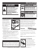
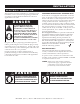
SAFETY PROCEDURES AND PRECAUTIONS Knowledge of proper procedures is essential to the safe operation of electrically and/or gas energized equipment. In accordance with generally accepted product safety labeling guidelines for potential hazards, the following signal words and symbols may be used throughout this manual. DANGER Used to indicate the presence of a hazard that WILL cause severe personal injury, death, or substantial property damage if the warning included with this symbol is ignored.
INSTALLATION DANGER CAUTION IMPROPER INSTALLATION, ALTERATION, ADJUSTMENT, SERVICE, OR MAINTENANCE COULD RESULT IN SEVERE INJURY, DEATH, OR CAUSE PROPERTY DAMAGE. METAL PARTS OF THIS EQUIPMENT BECOME EXTREMELY HOT WHEN IN OPERATION. TO AVOID BURNS, ALWAYS USE HAND PROTECTION WHEN OPERATING THIS APPLIANCE. READ THE INSTALLATION, OPERATING AND MAINTENANCE INSTRUCTIONS THOROUGHLY BEFORE INSTALLING OR SERVICING THIS EQUIPMENT.
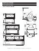
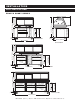
26-1/2" (672mm) ELECTRI 26- ELECTRICAL OUTLET 60" (1524mm) 3" (76mm) ADJUSTABLE ELECTRICAL PANEL INSTALLATION 47-11/16" (1212mm) 21-5/16" (540mm) 47-11/16" (1212 3" (76mm) ADJUSTABLE PEGS IN EACH CORNER ELECTRICAL OUTLET S IPEGS T EIN EACH I NCORNER STALLATION 60" (1524mm) 2-1/2" (63mm) 30" (763mm) 47-3/8" (1202mm) ELECTRICAL PANEL ELECTRICAL PANEL 26-1/2" (672mm) 25-9/16" (650mm) 25-9/16" (650mm) 36-5/8" (929mm) 36-5/8" (929mm) 37-1/2" (952mm) ED2SYS PROFILE 25-9/16" (650mm) 36-5/8"
INSTALLATION SITE INSTALLATION 5-1/2" (140mm) Swivel Caster Rigid Caster 5-1/2" (140mm) EU2SYS-48 32-1/2" (824mm) 48" (1219mm) 5-1/2" (140mm) Swivel Caster Swivel Caster Rigid Caster OPENING HEIGHT 28-5/16" (719mm) (Shown with optional shelf) OPENING ELECTRICAL OUTLET OPENING WIDTH 13-5/8" (346mm) (Shown with optional shelf) 26-1/4" (666mm) OPENING OPENING WIDTH 13-5/8" (346mm) 26-1/4" (666mm) ELECTRICAL PANEL 58-3/16" (1477mm) 31-5/8" (804mm) 26-1/2" (673mm) EU2SYS PROFILE EU2SY
INSTALLATION SITE INSTALLATION EU2SYS SHORT SERIES Swivel Caster 5-1/2" (140mm) 5-1/2" (140mm) EU2SYS-48 SHORT 32-1/2" (824mm) 48" (1219mm) 5-1/2" (140mm) Swivel Caster Rigid Caster Swivel Caster 5-1/2" (140mm) EU2SYS-72 SHORT (Shown with optional shelf) (Shown with optional shelf) ELECTRICAL OUTLET Swivel Caster Swivel Caster 96" (2438mm) Rigid Caster OPENING HEIGHT (Shown with optional shelf) 23-1/2" (596mm) OPENING WIDTH OPENING 26-1/4" (666mm) OPENING WIDTH OPENING 26-1/4" (66
INSTALLATION ELECTRICAL CONNECTION The appliance must be installed by a qualified service technician. The oven must be properly grounded in accordance with the National Electrical Code and applicable local codes. DANGER To avoid electrical shock, this appliance MUST be adequately grounded in accordance with local electrical codes or, in the absence of local codes, with the current edition of the National Electrical Code ANSI/ NFPA No. 70.
INSTALLATION ELECTRICAL CONNECTION Wir e d ia g r a m s a r e lo ca ted i n the l i terature package that came w i th the uni t. ED2(SY S ) S ERI ES ELEC T RI C AL 48 Series VOLTAGE PHASE CYCLE / HZ AMPS KW 120/208-240 208 240 1 1 1 50/60 50/60 50/60 13.8 11.6 13.0 3.3 2.5 3.1 230 1 50/60 12.6 2.
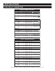
INSTALLATION FACTORY INSTALLED OPTIONS DESCRIPTION ED2-48 SERIES ED2-72 SERIES ED2-96 SERIES independent electrical outlet 5001781 5001781 5001781 temperature probe 5004916 5004917 5004918 ED2-48 SERIES ED2-72 SERIES ED2-96 SERIES butting kit, counter top 5015249 5015249 5015249 butting kit, system 5008523 5008523 5008523 carving station 5001874 5001874 5001874 5" (127mm), rigid CS-2025 (2 req'd) CS-2025 (2 req'd) CS-2025 (2 req'd) 5" (127mm), swivel with brake CS-2026 (2 req
OPERATING INSTRUCTIONS USER SAFETY INFORMATION CAUTION METAL PARTS OF THIS EQUIPMENT BECOME EXTREMELY HOT WHEN IN OPERATION. TO AVOID BURNS, ALWAYS USE HAND PROTECTION WHEN OPERATING THIS APPLIANCE. The Alto-Shaam heated display case is intended for use in commercial establishments by qualified operating personnel where all operators are familiar with the purpose, limitations, and associated hazards of this appliance.
OPERATING INSTRUCTIONS OPERATING PROCEDURES 1. DO NOT ADD WATER TO DISPLAY CASE Halo Heat display cases maintain a constant but gentle temperature and eliminate much of the moisture loss associated with conventional display cases. Because of this gentle heat, it is not necessary to add water to the display case. As a matter of fact, adding water is not recommended since water will accelerate the deterioration of the product, and may damage the unit voiding the warranty. 2.
OPERATING INSTRUCTIONS PAN CONFIGURATIONS • HEATED DISPLAY CASES Full-Service Units 48 MODELS 3 PAN ZONES ONE-HALF SIZE PAN FULL-SIZE PAN GN 1/4 ONE-THIRD SIZE PAN GN 1/3 1 5 GN 1/4 ONE-THIRD SIZE PAN 7 PAN ZONES 5 PAN ZONES ONE-THIRD SIZE PAN TWO-THIRDS SIZE PAN GN 1/2 GN 1/1 96 MODELS 72 MODELS GN 2/3 ONE-THIRD SIZE PAN ONE-THIRD SIZE PAN ONE-THIRD SIZE PAN ONE-THIRD SIZE PAN ONE-THIRD SIZE PAN 7 4 8 96 MODELS Self-Service Units 72 MODELS (72-/PL & 72-/PR) (96-/PL & 96-/PR) 3 PA
OPERATING INSTRUCTIONS GENERAL HOLDING GUIDELINES Chefs, cooks and other specialized food service personnel employ varied methods of cooking. Proper holding temperatures for a specific food product must be based on the moisture content of the product, product density, volume, and proper serving temperatures. Safe holding temperatures must also be correlated with palatability in determining the length of holding time for a specific product.
CARE AND CLEANING CLEANING AND PREVENTATIVE MAINTENANCE PROTECTING STAINLESS STEEL SURFACES CLEANING AGENTS It is important to guard against corrosion in the care of stainless steel surfaces. Harsh, corrosive, or inappropriate chemicals can completely destroy the protective surface layer of stainless steel. Abrasive pads, steel wool, or metal implements will abrade surfaces causing damage to this protective coating and will eventually result in areas of corrosion.
CARE AND CLEANING EQUIPMENT CARE Under normal circumstances, this appliance should provide you with long and trouble free service. There is no preventative maintenance required, however, the following Equipment Care Guide will maximize the potential life and trouble free operation of this appliance. The cleanliness and appearance of this equipment will contribute considerably to operating efficiency and savory, appetizing food. Good equipment that is kept clean works better and lasts longer.
SANITATION Food flavor and aroma are usually so closely related that it is difficult, if not impossible, to separate them. There is also an important, inseparable relationship between cleanliness and food flavor. Cleanliness, top operating efficiency, and appearance of equipment contribute considerably to savory, appetizing foods. Good equipment that is kept clean, works better and lasts longer. Most food imparts its own particular aroma and many foods also absorb existing odors.
SERVICE CABLE REPLACEMENT KITS 48 SERIES CABLE REPLACEMENT KIT CABLE HEATING SERVICE KIT NO. 4880 INCLUDES: CB-3045 CABLE HEATING ELEMENT ...................................134 FEET CR-3226 RING CONNECTOR IN-3488 INSULATION CORNER ............................................ 1 FOOT BU-3105 SHOULDER BUSHING BU-3106 CUP BUSHING ............................................................. 4 SL-3063 INSULATING SLEEVE .....................................................
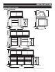
SERVICE FULL ASSEMBLY • FRONT VIEW (ED2-96 SHOWN) 11 1 8 2 2 7 3 5 6 28 29 11 4 31 9 32 10 7 30 16 24 16 23 27 26 14 12 13 17 19 18 4 17 16 25 20 16 21 22 33 34 35 36 37 38 P art numbe rs a nd dra wings ar e s ubjec t t o c hange w i t h o u t n o t i c e .
SERVICE FULL ASSEMBLY • FRONT VIEW M OD E L > ITE M 1 2 3 4 5 6 7 8 9 10 11 12 13 14 15 16 17 18 19 20 21 22 23 24 25 26 27 28 29 30 31 32 33 34 35 36 37 38 39* 40* 41* 42* * D ESC R I PT I O N DOOR GLASS, LH DOOR GLASS, MIDDLE DOOR GLASS, RH DOOR TRACK, BOTTOM UPRIGHT ANGLED SUPPORT UPRIGHT WEDGE GASKET, END GLASS FRONT GLASS** BRACKET, CUTTING BOARD *CUTTING BOARD BRACKET, CUTTING BOARD BULB 120V/208-240V; 100WATT 120V/208-240V; 65WATT 230V; 100WATT END GLASS, CLEAR END PANEL, RH*** black WELL, CABLE
SERVICE FULL LIST OF COUNTER-TOP PANELS (see MODEL > ITE M 13 21 22 23 24 28 D ESC R I PT I O N GLASS FRAME, RH REAR TRIM RIGHT TRIM FRONT TRIM LEFT TRIM GLASS FRAME, LH E D 2 ( S Y S ) -4 8 18) drawing pg E D 2 ( S Y S ) -7 2 E D 2( SYS) - 96 PART NO. QTY PART NO. QTY P A R T NO.
SERVICE SUBSTITUTE PARTS FOR SELF-SERVE UNITS M O D EL > * NOT SHOWN ITE M D ESC R I PT I O N ED2(SYS) -4 8 / P -7 2 / P - 7 2 / P L, / P R - 96/P L , /P R PART NO.
SERVICE BASE ASSEMBLY (ED2SYS-96 SHOWN) 1 12 11 11 10 13 2 3 control panel rear view (access panel removed) 9 4 8 6 5 7 M OD E L > ITE M D ESCR I PT I O N E D 2 ( S Y S ) -7 2 E D 2( SYS) - 96 PART NO. QTY PART NO. QTY P A R T NO.
SERVICE INNER TOP ASSEMBLY (ED2-96 SHOWN) 8 7 9 3 6 5 1 1 11 10 4 2 9 2 3 3 4 5 service hinge kit ITEM 6 8 7 service hinge kit * not shown CAP, END, RH 2 UPPER DOOR FILLER 3 SERVICE HINGE KIT (SEE INSET) 4 LAMP RECEPTACLE LAMP RECEPTACLE ITEM D E S C R I P TI ON QTY 25° HINGE 2 7 MOUNTING BLOCKS 2 2 GAS RAM PINS 2 8 HOLE PLUG 2 3 HINGE PIN 1 9 HINGE BOLT 2 4 PIN PLUG 6 10 LOCK WASHERS 2 5 LOWER GAS RAM PIN 1 11 GAS RAM HOLDER 2 6 MOUNTING PIN 1 D ESC R I P
SERVICE FULL ASSEMBLY (BU2-96 SHOWN) 1 2 3 18 17 4 5 16 6 15 7 14 10 9 8 13 12 M OD E L > 11 B U 2 -4 8 BU2-72 BU2- 96 PART NO. QTY PART NO. QTY P A R T NO.
SERVICE FULL ASSEMBLY (BU2-96 SHORT SHOWN) 1 2 18 3 17 4 5 16 6 15 7 14 10 13 12 M OD E L > ITE M D ESC R I PT I O N 1 TOP FRAME 2 CENTER PANEL 3 CORD FOR 4" BOX FAN 4 CORNER PANELS 5 REAR SHELF SUPPORT 6 SIDE & REAR BLACK PANELS customer side 11 9 8 BU2-48 SHORT B U 2 -7 2 S H O R T B U 2- 96 SHORT PART NO. QTY PART NO. QTY P A R T NO.
M N -2 8 8 2 0 (R e v 1 ) • 0 5 /1 4 • E D 2 & E U 2 S eri es Operati on & C are Manual • 26
M N -2 8 8 2 0 (R e v 1 ) • 0 5 /1 4 • E D 2 & E U 2 S eri es Operati on & C are Manual • 27
M N -2 8 8 2 0 (R e v 1 ) • 0 5 /1 4 • E D 2 & E U 2 S eri es Operati on & C are Manual • 28
M N -2 8 8 2 0 (R e v 1 ) • 0 5 /1 4 • E D 2 & E U 2 S eri es Operati on & C are Manual • 29
M N -2 8 8 2 0 (R e v 1 ) • 0 5 /1 4 • E D 2 & E U 2 S eri es Operati on & C are Manual • 30
M N -2 8 8 2 0 (R e v 1 ) • 0 5 /1 4 • E D 2 & E U 2 S eri es Operati on & C are Manual • 31
M N -2 8 8 2 0 (R e v 1 ) • 0 5 /1 4 • E D 2 & E U 2 S eri es Operati on & C are Manual • 32
M N -2 8 8 2 0 (R e v 1 ) • 0 5 /1 4 • E D 2 & E U 2 S eri es Operati on & C are Manual • 33
M N -2 8 8 2 0 (R e v 1 ) • 0 5 /1 4 • E D 2 & E U 2 S eri es Operati on & C are Manual • 34
M N -2 8 8 2 0 (R e v 1 ) • 0 5 /1 4 • E D 2 & E U 2 S eri es Operati on & C are Manual • 35
M N -2 8 8 2 0 (R e v 1 ) • 0 5 /1 4 • E D 2 & E U 2 S eri es Operati on & C are Manual • 36
M N -2 8 8 2 0 (R e v 1 ) • 0 5 /1 4 • E D 2 & E U 2 S eri es Operati on & C are Manual • 37
M N -2 8 8 2 0 (R e v 1 ) • 0 5 /1 4 • E D 2 & E U 2 S eri es Operati on & C are Manual • 38
M N -2 8 8 2 0 (R e v 1 ) • 0 5 /1 4 • E D 2 & E U 2 S eri es Operati on & C are Manual • 39
M N -2 8 8 2 0 (R e v 1 ) • 0 5 /1 4 • E D 2 & E U 2 S eri es Operati on & C are Manual • 40
TRANSPORTATION DAMAGE and CLAIMS 1. 2. 3. 4. 5. 6. 7. 8. All Alto-Shaam equipment is sold F.O.B. shipping point, and when accepted by the carrier, such shipments become the property of the consignee. Should damage occur in shipment, it is a matter between the carrier and the consignee. In such cases, the carrier is assumed to be responsible for the safe delivery of the merchandise, unless negligence can be established on the part of the shipper.