Heated Display Cases Full Service or Self Service Models: EC2SYS-48 EC2(SYS)-48 SERIES EC2(SYS)-72 SERIES EC2(SYS)-96 SERIES EC2-48 HN2(SYS)-48 SERIES HN2(SYS)-72 SERIES HN2(SYS)-96 SERIES HN2SYS-72 HN2-72 T Y2(SYS)-48 SERIES TY2(SYS)-72 SERIES TY2(SYS)-96 SERIES • INSTALLATION TY2SYS-96 TY2-96 • OPERATION • MAINTENANCE W164 N9221 Water Street • P.O. Box 450 • Menomonee Falls, Wisconsin 53052-0450 USA PHONE: 262.251.3800 • 800.558.8744 USA / CANADA FAX: 262.251.7067 • 800.329.8744 U . S . A .
Delivery . . . . . . . . . . . . . . . . . . . . . . . . . . . . . . . . . . 1 Unpacking . . . . . . . . . . . . . . . . . . . . . . . . . . . . . . . . 1 Safety Procedures and Precautions . . . . . . . . . . . . . 2 Installation Installation Requirements . . . . . . . . . . Clearance Requirements . . . . . . . . . . . Leveling . . . . . . . . . . . . . . . . . . . . . . . .
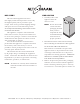
DELIVERY UNPACKING This Alto-Shaam appliance has been thoroughly tested and inspected to ensure only the highest quality unit is provided. Upon receipt, check for any possible shipping damage and report it at once to the delivering carrier. See Transportation Damage and Claims section located in this manual. This appliance, complete with unattached items and accessories, may have been delivered in one or more packages.
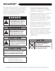
SAFETY PROCEDURES AND PRECAUTIONS Knowledge of proper procedures is essential to the safe operation of electrically and/or gas energized equipment. In accordance with generally accepted product safety labeling guidelines for potential hazards, the following signal words and symbols may be used throughout this manual. DANGER Used to indicate the presence of a hazard that WILL cause severe personal injury, death, or substantial property damage if the warning included with this symbol is ignored.
INSTALLATION DANGER CAUTION IMPROPER INSTALLATION, ALTERATION, ADJUSTMENT, SERVICE, OR MAINTENANCE COULD RESULT IN SEVERE INJURY, DEATH, OR CAUSE PROPERTY DAMAGE. METAL PARTS OF THIS EQUIPMENT BECOME EXTREMELY HOT WHEN IN OPERATION. TO AVOID BURNS, ALWAYS USE HAND PROTECTION WHEN OPERATING THIS APPLIANCE. READ THE INSTALLATION, OPERATING AND MAINTENANCE INSTRUCTIONS THOROUGHLY BEFORE INSTALLING OR SERVICING THIS EQUIPMENT.
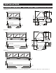
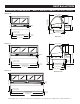
INSTALLATION EXTERIOR DIMENSIONS - EC2 & EC2SYS SERIES (standard height) EC2SYS-48 53-3/16" (1350mm) 10" (252mm) 27-3/16" (690mm) WELL 6-13/16" (172mm) 28-1/2" (721mm) CL LEVELING SCREWS 3" (76mm) ADJUSTABLE PEGS IN EACH CORNER 37-3/4" (958mm) 2-5/16" (58mm) ELECTRICAL CORD Cord Length: 7' (2133mm) 9-1/2" (242mm) WELL HEIGHT 48" (1218mm) 8" (202mm) 13-9/16" (344mm) CUTTING BOARD HEIGHT 1-1/2" (35mm) 32-11/16" (830mm) 43-1/4" (1098mm) 1-3/16" (30mm) 45-11/16" (1160mm) CL LEVELING SCREWS 48
INSTALLATION EXTERIOR DIMENSIONS - EC2 & EC2SYS SERIES (optional height) EC2SYS-48 53-3/16" (1350mm) 10" (252mm) 27-3/16" (690mm) WELL 6-13/16" (172mm) 28-1/2" (721mm) CL LEVELING SCREWS 37-3/4" (958mm) 2-5/16" (58mm) ELECTRICAL CORD Cord Length: 7' (2133mm) 9-1/2" (242mm) WELL HEIGHT 52-1/4" (1326mm) 8" (202mm) 13-9/16" (344mm) CUTTING BOARD HEIGHT 1-1/2" (35mm) 32-11/16" (830mm) 3" (76mm) ADJUSTABLE PEGS IN EACH CORNER 43-1/4" (1098mm) 1-3/16" (30mm) 45-11/16" (1160mm) CL LEVELING SCRE
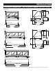
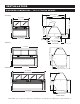
INSTALLATION EXTERIOR DIMENSIONS - HN2 & HN2SYS SERIES (standard HN2SYS-48 height) 51-3/8" (1304mm) 10" (252mm) 13-9/16" (344mm) CUTTING BOARD HEIGHT 27-3/16" (690mm) WELL 6-13/16" (172mm) 37-3/4" (958mm) 2-5/16" (58mm) ELECTRICAL CORD Cord Length: 7' (2133mm) 9-1/2" (242mm) WELL HEIGHT 52-1/4" (1326mm) 8" (202mm) 28-1/2" (721mm) CL LEVELING SCREWS 1-1/2" (35mm) 41-7/16" (1052mm) 3" (76mm) ADJUSTABLE PEGS IN EACH CORNER 1-3/16" (30mm) 45-11/16" (1160mm) CL LEVELING SCREWS 48" (1219mm) HN
INSTALLATION EXTERIOR DIMENSIONS - HN2 & HN2SYS SERIES (optional HN2SYS-48 height) 51-3/8" (1304mm) 10" (252mm) 13-9/16" (344mm) CUTTING BOARD HEIGHT 27-3/16" (690mm) WELL 6-13/16" (172mm) 28-1/2" (721mm) CL LEVELING SCREWS 3" (76mm) ADJUSTABLE PEGS IN EACH CORNER 37-3/4" (958mm) 2-5/16" (58mm) ELECTRICAL CORD Cord Length: 7' (2133mm) 9-1/2" (242mm) WELL HEIGHT 48" (1218mm) 8" (202mm) 1-1/2" (35mm) 41-7/16" (1052mm) 1-3/16" (30mm) 45-11/16" (1160mm) CL LEVELING SCREWS 48" (1219mm) HN2 Pro
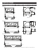
INSTALLATION EXTERIOR DIMENSIONS - TY2 & TY2SYS SERIES 64-7/8" (1647mm) TY2SYS-48 52-13/16" (1341mm) 58-7/8" (1495mm) 48" (1219mm) 50" (1270mm) SYS-48 11-5/8" (294mm) 29-5/8" (753mm) 33-7/16" (849mm) ELECTRICAL PANEL 52-3/16" (1325mm) 108° Cord Position from back*: 2-3/8" (60mm) 3-13/16" (96mm) WITH OPTIONAL END PANELS Cord Position from right side*: 6-7/8" (174mm) CORD LENGTH: 7' (2133mm) 39-3/8" (1000mm) 49-5/8" (1260mm) TY2SYS-72 TY2 Profile *Cord postion is from operator side TY2 S
INSTALLATION ELECTRICAL CONNECTION The appliance must be installed by a qualified service technician. The oven must be properly grounded in accordance with the National Electrical Code and applicable local codes. DANGER To avoid electrical shock, this appliance MUST be adequately grounded in accordance with local electrical codes or, in the absence of local codes, with the current edition of the National Electrical Code ANSI/ NFPA No. 70.
INSTALLATION ELECTRICAL CONNECTION Wir e d ia g r a m s a r e lo ca ted i n the l i terature package that came w i th the uni t. E C 2 & HN2 S ERI ES ELECTRI CA L 48 Series VOLTAGE PHASE CYCLE / HZ AMPS KW 120/208-240 208 240 1 1 1 50/60 50/60 50/60 13.8 11.6 13.0 3.3 2.5 3.1 230 1 50 12.6 2.
INSTALLATION FACTORY INSTALLED OPTIONS DESCRIPTION EC2 SERIES HN2 SERIES TY2 SERIES 5001781 5001781 5001781 48 series 5004916 5004916 5004916 72 series 5004917 5004917 5004917 96 series 5004918 5004918 5004918 EC2 SERIES HN2 SERIES TY2 SERIES butting kit, counter top 5015253 5009003 5015250 butting kit, system 5009004 5009003 5009001 — — 5001874 PN-25752 PN-25752 PN-25752 48 series 1001990 1001990 1001990 72 series 1001991 1001991 1001991 55265 55265 55265 -48,
OPERATING INSTRUCTIONS USER SAFETY INFORMATION CAUTION METAL PARTS OF THIS EQUIPMENT BECOME EXTREMELY HOT WHEN IN OPERATION. TO AVOID BURNS, ALWAYS USE HAND PROTECTION WHEN OPERATING THIS APPLIANCE. The Alto-Shaam heated display case is intended for use in commercial establishments by qualified operating personnel where all operators are familiar with the purpose, limitations, and associated hazards of this appliance.
OPERATING INSTRUCTIONS OPERATING PROCEDURES 1. DO NOT ADD WATER TO DISPLAY CASE Halo Heat display cases maintain a constant but gentle temperature and eliminate much of the moisture loss associated with conventional display cases. Because of this gentle heat, it is not necessary to add water to the display case. As a matter of fact, adding water is not recommended since water will accelerate the deterioration of the product, and may damage the unit voiding the warranty. 2.
OPERATING INSTRUCTIONS PAN CONFIGURATIONS • HEATED DISPLAY CASES Full-Service Units 48 MODELS 3 PAN ZONES ONE-HALF SIZE PAN FULL-SIZE PAN GN 1/4 1 5 ONE-THIRD SIZE PAN GN 1/3 GN 1/4 ONE-THIRD SIZE PAN 7 PAN ZONES 5 PAN ZONES ONE-THIRD SIZE PAN TWO-THIRDS SIZE PAN GN 1/2 GN 1/1 96 MODELS 72 MODELS GN 2/3 ONE-THIRD SIZE PAN ONE-THIRD SIZE PAN ONE-THIRD SIZE PAN ONE-THIRD SIZE PAN ONE-THIRD SIZE PAN 7 4 8 96 MODELS Self-Service Units 72 MODELS (72-/PL & 72-/PR) (96-/PL & 96-/PR) 3 P
OPERATING INSTRUCTIONS GENERAL HOLDING GUIDELINES Chefs, cooks and other specialized food service personnel employ varied methods of cooking.
CARE AND CLEANING CLEANING AND PREVENTATIVE MAINTENANCE PROTECTING STAINLESS STEEL SURFACES It is important to guard against corrosion in the care of stainless steel surfaces. Harsh, corrosive, CLEANING AGENTS Use non-abrasive cleaning products designed for use on stainless steel surfaces. Cleaning agents must be chloride-free compounds and must not or inappropriate chemicals can completely destroy the contain quaternary salts. Never use hydrochloric acid (muriatic acid) on stainless steel surfaces.
CARE AND CLEANING EQUIPMENT CARE Under normal circumstances, this appliance should provide you with long and trouble free service. There is no preventative maintenance required, however, the following Equipment Care Guide will maximize the potential life and trouble free operation of this appliance. The cleanliness and appearance of this equipment will contribute considerably to operating efficiency and savory, appetizing food. Good equipment that is kept clean works better and lasts longer.
SANITATION Food flavor and aroma are usually so closely related that it is difficult, if not impossible, to separate them. There is also an important, inseparable relationship between cleanliness and food flavor. Cleanliness, top operating efficiency, and appearance of equipment contribute considerably to savory, appetizing foods. Good equipment that is kept clean, works better and lasts longer. Most food imparts its own particular aroma and many foods also absorb existing odors.
SERVICE EC2(SYS) SERIES - COUNTER TOP ASSEMBLY (EC2-96 SHOWN) 1 2 3 4 5 24 7 8 10 23 9 11 12 13 21 14 22 21 20 19 18 16 17 15 2 Par t num ber s and dr a w i n g s a r e s u b j e c t t o c h a n g e w i t h o u t n o t i c e .
SERVICE EC2(SYS) SERIES - COUNTER TOP ASSEMBLY (PARTS LIST) M OD E L > ITE M E C 2 ( S Y S ) -7 2 E C 2( SYS) - 96 PART NO. QTY PART NO. QTY P A R T NO.
SERVICE EC2(SYS) SERIES - SUBSTITUTE PARTS FOR SELF-SERVE UNITS M O D EL > ITE M 1 D ESC R I PT I O N GLASS FRONT full-serve self-serve EC2(SYS) -4 8 / P -7 2 / P -7 2 / P L, / P R - 96/P L , /P R PART NO.
SERVICE EC2(SYS) SERIES - ELECTRICAL ASSEMBLY (EC2-96 SHOWN) 1 2 3 4 5 6 7 8 9 11 10 M OD E L > ITE M 1 D ESC R I PT I O N LAMP RECEPTACLE 2 BULB 3 SWITCH, TOGGLE SWITCH, BOOT 4 INDICATOR LIGHT 5 THERMOSTAT 6 BUSHING, STRAIN RELIEF 7 TERMINAL BLOCK QTY P A R T NO.
SERVICE EC2(SYS) SERIES - BASE ASSEMBLY (EC2SYS-96 SHOWN) 1 2 3 10 8 7 6 9 5 4 M O DE L > ITE M 1 D ESCR I PT I O N END PANEL, RH 2 LOWER END PANEL, REAR 3 END PANEL, LH 4 7 8 E C 2( SYS) - 96 PART NO. QTY P A R T NO.
SERVICE HN2(SYS) SERIES - COUNTER TOP ASSEMBLY (HN2-96 SHOWN) 1 2 3 4 5 7 24 6 8 10 23 9 11 12 13 14 21 22 21 20 19 16 18 15 2 17 Par t num ber s and dr a w i n g s a r e s u b j e c t t o c h a n g e w i t h o u t n o t i c e .
SERVICE HN2(SYS) SERIES - COUNTER TOP ASSEMBLY (PARTS LIST) M OD E L > ITE M D ESC R I PT I O N H N 2 ( S Y S ) -4 8 H N 2 ( S Y S ) -7 2 PART NO. QTY H N 2( SYS) - 96 PART NO. QTY P A R T NO.
SERVICE HN2(SYS) SERIES - SUBSTITUTE PARTS FOR SELF-SERVE UNITS M O D EL > ITE M 1 D ESC R I PT I O N GLASS FRONT full-serve self-serve HN2(SYS) -4 8 / P -7 2 / P - 7 2 / P L, / P R - 96/P L , /P R PART NO.
SERVICE HN2(SYS) SERIES - ELECTRICAL ASSEMBLY (HN2-96 SHOWN) 1 2 3 4 5 6 7 8 9 11 10 M OD E L > ITE M 1 2 3 D ESC R I PT I O N LAMP RECEPTACLE BULB SWITCH, TOGGLE SWITCH, BOOT 4 INDICATOR LIGHT 5 THERMOSTAT 6 BUSHING, STRAIN RELIEF 7 TERMINAL BLOCK QTY PART NO. QTY P A RT NO.
SERVICE HN2(SYS) SERIES - BASE ASSEMBLY (HN2SYS-96 SHOWN) 1 2 3 10 8 9 7 6 5 4 M OD E L > ITE M 1 D ESCR I PT I O N END PANEL, RH black stainless steel custom color 2 3 LOWER END PANEL END PANEL, LH black stainless steel custom color 4 RISER, SIDE, 52-1/4" (1326mm) height black stainless steel custom color RISER, SIDE, 48" (1218mm) height black stainless steel custom color 5 RISER, FRONT/REAR, 52-1/4" (1326mm) height black stainless steel custom color RISER, FRONT/REAR, 48" (1218mm)
SERVICE SERVICE TY2(SYS) SERIES - COUNTER TOP ASSEMBLY (TY2-96 SHOWN) 1 27 26 25 2 23 20 24 3 7 21 19 22 5 4 6 8 7 9 18 10 11 15 34 13 12 16 14 17 28 29 30 31 32 33 Par t num ber s and dr a w i n g s a r e s u b j e c t t o c h a n g e w i t h o u t n o t i c e .
SERVICE M OD E L > ITE M 1 2 3 D ESC R I PT I O N OUTER TOP DOOR TRACK, UPPER CUTTING BOARD 4ft (1.22m) 6ft (1.83m) 4 5 6 7 8 9 10 11 CUTTING BOARD BRACKET BRACKET, CUTTING BOARD, SPACER END GLASS clear customer side, solar bronze (lh) customer side, solar bronze (rh) ELEMENT KIT GASKET, END GLASS INSULATION END PANEL black (rh/lh) stainless steel (rh) stainless steel (lh) custom color 12 13 14 15 16 ACCESS COVER LEG BRACE WELD LEGS FRONT DECOR PANEL CORD 7' (2.
SERVICE TY2(SYS) SERIES - SUBSTITUTE PARTS FOR SELF-SERVE UNITS M O D EL > ITE M 1 D ESC R I PT I O N GLASS FRONT full-serve self-serve TY 2 ( S Y S ) -4 8 / P -7 2 / P - 7 2 / P L, / P R - 96/P L , /P R PART NO.
SERVICE TY2(SYS) SERIES - INNER TOP ASSEMBLY (TY2-96 SHOWN) 1 1 6 2 3 1 5 4 M OD E L > ITE M D ESC R I PT I O N TY2(SYS)-48 TY2(SYS)-72 T Y2( SYS) - 96 PART NO. QTY PART NO. QTY P A R T NO.
SERVICE TY2(SYS) SERIES - BASE ASSEMBLY (TY2SYS-96 SHOWN) 13 11 9 10 12 8 10 11 7 6 control panel rear view 1 2 5 4 3 MODEL > D ESCR I PT I O N ITE M 1 FRAME WELD 2 END PANEL, RH 3 BUMPER, END CAP 4 BUMPER TRACK 5 BUMPER RAIL 6 TY2(SYS)-72 T Y 2( SYS) - 96 PART NO. QTY PART NO. QTY P A R T NO.
SERVICE CABLE REPLACEMENT KITS 48 SERIES C A B LE REPLACEMENT KIT CABLE HEATING SERVICE KIT NO. 4880 INCLUDES: CB-3045 CABLE HEATING ELEMENT ...................................134 FEET CR-3226 RING CONNECTOR IN-3488 INSULATION CORNER ............................................ 1 FOOT BU-3105 SHOULDER BUSHING BU-3106 CUP BUSHING ............................................................. 4 SL-3063 INSULATING SLEEVE .....................................................
M N- 29390 - R e v 2 (0 5 /1 4 ) • E C 2 (S YS ), HN 2(S Y S ) & TY 2(S Y S ) S eri es Operati on & C are Manual • 35
M N- 29390 - R e v 2 (0 5 /1 4 ) • E C 2 (S YS ), HN 2(S Y S ) & TY 2(S Y S ) S eri es Operati on & C are Manual • 36
M N- 29390 - R e v 2 (0 5 /1 4 ) • E C 2 (S YS ), HN 2(S Y S ) & TY 2(S Y S ) S eri es Operati on & C are Manual • 37
M N- 29390 - R e v 2 (0 5 /1 4 ) • E C 2 (S YS ), HN 2(S Y S ) & TY 2(S Y S ) S eri es Operati on & C are Manual • 38
M N- 29390 - R e v 2 (0 5 /1 4 ) • E C 2 (S YS ), HN 2(S Y S ) & TY 2(S Y S ) S eri es Operati on & C are Manual • 39
M N- 29390 - R e v 2 (0 5 /1 4 ) • E C 2 (S YS ), HN 2(S Y S ) & TY 2(S Y S ) S eri es Operati on & C are Manual • 40
M N- 29390 - R e v 2 (0 5 /1 4 ) • E C 2 (S YS ), HN 2(S Y S ) & TY 2(S Y S ) S eri es Operati on & C are Manual • 41
M N- 29390 - R e v 2 (0 5 /1 4 ) • E C 2 (S YS ), HN 2(S Y S ) & TY 2(S Y S ) S eri es Operati on & C are Manual • 42
M N- 29390 - R e v 2 (0 5 /1 4 ) • E C 2 (S YS ), HN 2(S Y S ) & TY 2(S Y S ) S eri es Operati on & C are Manual • 43
M N- 29390 - R e v 2 (0 5 /1 4 ) • E C 2 (S YS ), HN 2(S Y S ) & TY 2(S Y S ) S eri es Operati on & C are Manual • 44
M N- 29390 - R e v 2 (0 5 /1 4 ) • E C 2 (S YS ), HN 2(S Y S ) & TY 2(S Y S ) S eri es Operati on & C are Manual • 45
M N- 29390 - R e v 2 (0 5 /1 4 ) • E C 2 (S YS ), HN 2(S Y S ) & TY 2(S Y S ) S eri es Operati on & C are Manual • 46
TRANSPORTATION DAMAGE and CLAIMS 1. 2. 3. 4. 5. 6. 7. 8. All Alto-Shaam equipment is sold F.O.B. shipping point, and when accepted by the carrier, such shipments become the property of the consignee. Should damage occur in shipment, it is a matter between the carrier and the consignee. In such cases, the carrier is assumed to be responsible for the safe delivery of the merchandise, unless negligence can be established on the part of the shipper.