
Specifications


COMBITHERM CT PROFORMANCE AND CT CLASSIC SERIES • INSTALLATION MANUAL • MN-35947 • 55.
COMBITHERM® POST INSTALLATION CHECKLIST
CUSTOMER INFORMATION:
Street Address:
Date of Installation:
Customer Name: City:
State: Zip:
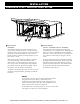
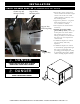
CLEARANCES:
Write the actual measured distances in the boxes provided:
Left:
Back:
0" (0mm) required - 18" (457mm) recommended for
service access
4" (102mm) required
Right: Top:
0" (0mm) from non-combustible surfaces;
2" (51mm) from combustible surfaces
20" (508mm) required
Are all clearance requirements met?
❑ ❑
WATER SUPPLY AND DRAINS:
Verify hook up of two (2) separate water lines with a 3/4" (19mm) Water connection supply line. Verify Inlet water
pressure is at a minimum of 30 PSI (2.1 bar). Maximum water pressure is not to exceed 90 PSI (6.3 bar).
Alto-Shaam has listed water quality requirements in the installation manual for this equipment. It is the responsibility of the
end user to have the water being connected to this appliance tested to ensure it meets with these standards. Failure to meet with
these standards can void the warranty of the equipment if water quality is found to be the reason of the failure.
Has a filtration system been installed?
❑ ❑
Type?
Has a complete water Analysis been complete?
❑ ❑
Static water pressure:
ELECTRICAL CONNECTIONS:
Rated Voltage: Rated Phase:
Breaker Size:
Actual Voltage:
L1-N L2-N L3-N L1-L2 L1-L3 L2-L3
Gas Connections
Rated Gas Supply Nat LP Actual Gas Supplied Nat LP
Improper drain connections can result in equipment failure. Alto-Shaam drain requirements are located in the installation
manual for this equipment. Failure to meet these standards can void warranty if the failure is found to have been caused by an
improperly connected drain. It is the responsibility of the installer to ensure the manufactures requirements are met in the plumbing of
the drain system.
DRAIN:
Type of material used for drain?
Is a 2" (51mm) air gap installed?
❑ ❑
Is the air gap within 12" (305mm) of the CombiOven?
❑ ❑
Is the drain piped with a positive descending slope?
❑ ❑
Use the diagrams provided to crate a simple diagram showing how the drain plumbing is ran. Include measurements showing
the distance to the floor drain, location of the air gap, and venting of the drain. Drain plumbing requirements can be found in the
installation manual.
NOTES:
COMBITHERM® POST INSTALLATION CHECKLIST CONTINUED
POWER ON:
Current factory software versions:
IB
❑ OB ❑ CB ❑
Record software version installed:
IB
❑ OB ❑ CB ❑
FUNCTION TEST:
Cycle Y1 Operation fi ll/Steam injection
❑ ❑
Cycle Y2 Operation condensate cooling valve
❑ ❑
Cycle Y3 Operation rinse solenoid valve
❑ ❑
Dynamic water pressure with Y1 Dynamic water pressure with Y3
Dynamic water pressure with Y2
Start oven in steam mode and record Amperage L1 L2 L3
Start oven in convection and record Amperage L1 L2 L3
GAS OVENS:
With the burner on, check the following: Dynamic pressure to the valve
Flue gas analysis: Co2% Co pmm
INSTALLATION COMPLETE:
Clean up job site
❑ ❑
Wipe down and clean exterior of CombiOven
❑ ❑
Picture of screen displaying current software versions
❑ ❑
Picture of drain with air gap
❑ ❑
Picture of water connections at CombiOven connections
❑ ❑
Picture of gas line and connections at CombiOven
❑ ❑
Picture of unit in place with surrounding equipment
❑ ❑
COMPANY INFORMATION:
Company Name: Installing Technician:
Street Address: City: Zip:
Technician Signature: Print Name:
Customer Signature: Print Name:
Bottom 5-1/8" (130mm)
Top 20" (508mm)
Back 4" (102mm)
Right side 0" (0mm) from non-combustible materials
Left side 0" (0mm)
Recommended 18" (457mm) for service access
2" (51mm) from combustible materials
Bottom 5-1/8" (130mm)
Top 20" (508mm)
Back 4" (102mm)
Right side 0" (0mm) from non-combustible materials
Left side 0" (0mm)
Recommended 18" (457mm) for service access
2" (51mm) from combustible materials