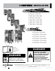
Installation CTP6-10e, CTP6-10G CTP10-10e, CTP10-10G CTP7-20e, CTP7-20G CTP10-20e, CTP10-20G CTP20-10e, CTP20-10G CTP20-20e, CTP20-20G CTC6-10e, CTC6-10G CTC10-10e, CTC10-10G CTC7-20e, CTC7-20G CTC10-20e, CTC10-20G CTC20-10e, CTC20-10G CTC20-20e, CTC20-20G Consult instructions for installation and use. DANGER IMPROPER INSTALLATION, ALTERATION, ADJUSTMENT, SERVICE, OR MAINTENANCE COULD RESULT IN SEVERE INJURY, DEATH, OR CAUSE PROPERTY DAMAGE.
Installation table of contents Delivery........................................................................... 1 Unpacking...................................................................... 1 Safety Procedures and Precautions............................... 2 Stand Installation..................................................... 34 Common Accessories.............................................. 35 Electrical Connection for Gas Models......................
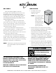
DELIVERY UNPACkING This Alto-Shaam appliance has been thoroughly tested and inspected to ensure only the highest quality unit is provided. Upon receipt, check for any possible shipping damage and report it at once to the delivering carrier. See Transportation Damage and Claims section located in this manual. This appliance, complete with unattached items and accessories, may have been delivered in one or more packages.
SAFETY PROCEDURES AND PRECAUTIONS Knowledge of proper procedures is essential to the safe operation of electrically and/or gas energized equipment. In accordance with generally accepted product safety labeling guidelines for potential hazards, the following signal words and symbols may be used throughout this manual. DANGER Used to indicate the presence of a hazard that WILL cause severe personal injury, death, or substantial property damage if the warning included with this symbol is ignored.
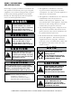
INSTALLATION SITE INSTALLATION DANGER IMPROPER INSTALLATION, ALTERATION, ADJUSTMENT, SERVICE, OR MAINTENANCE COULD RESULT IN SEVERE INJURY, DEATH, OR CAUSE PROPERTY DAMAGE. READ THE INSTALLATION, OPERATING AND MAINTENANCE INSTRUCTIONS THOROUGHLY BEFORE INSTALLING OR SERVICING THIS EQUIPMENT. DANGER AVERTISSEMENT : UNE INSTALLATION, UN AJUSTEMENT, UNE ALTÉRATION, UN SERVICE OU UN ENTRETIEN NON CONFORME AUX NORMES PEUT CAUSER DES DOMMAGES À LA PROPRIÉTÉ, DES BLESSURES OU LA MORT.
I N S T A L L A T I O N D uties & responsibilities - N ew construction Designer/Consultant Responsibilities: Pre-Installation Complete water analysis to be conducted to ensure water quality meets manufacture specifications. Proper floor drain within 6' (1829mm) of where the oven is to be installed. Two 3/4" cold water connections with individual shut offs within 3' (914mm) of the oven.
I N S T A L L A T I O N D uties & responsibilities - R etro F it / e x isting k itchen Designer/Consultant Responsibilities: Pre-Installation Complete water analysis to be conducted to ensure water quality meets manufacture specifications. Proper floor drain within 6' (1829mm) of where the oven is to be installed. Two 3/4" cold water connections with individual shut offs within 3' (914mm) of the oven.
COMBITHERM® PRE-INSTALLATION CHECkLIST Location Name: Date: Location Address: State/Zip Code: Building Name: Phone: Contact Name: E-mail: Install Company: Install Technician: Contact Info: Number of Combis Being Installed: Model Number Serial Number Check all clearances of doors, entryways, and hallways from delivery point to installation area.
COMBITHERM® PRE-INSTALLATION CHECkLIST CONTINUED OVEN CLEARANCES: Installation Clearances Back Side Left Side: Bottom: Right Right side side 0" 0" (0mm) (0mm) from from non-combustible non-combustible materials materials 2" 2" (51mm) (51mm) from from combustible combustible materials materials Right Side: Back 4" (102mm) Back 4" (102mm) Left Left side side 0" 0" (0mm) (0mm) Recommended Recommended 18"18" (457mm) (457mm) forfor service service access access Top 20" (508mm) Top 20" (508mm) Top: Bottom
Left side 0" (0m COMBITHERM® PRE-INSTALLATION CHECkLIST CONTINUED DRAIN: Is there a proper floor drain within 6' (1829mm) of the oven? ❑ YES ❑ NO Actual distance to floor drain: 6' (1829mm) Bottom 5-1/8" (130mm) Be sure to use best practices when routing the line to keep it as short as possible. The drain line should have a positive descending slope. Verify 1/8" (3.2mm) pitch to 10' (305cm) of drain line. COMMENTS: COMBITHERM CT PROFORMANCE AND CT CLASSIC SERIES • INSTALLATION MANUAL • MN-35947 • 8.
6.10 ELEC OVER ASC-4E: 1877mm x 1111mm x 1182mm 6.
6.10 ELEC OVER 10.10 ELEC: 1850mm x 907mm x 995mm 6.10 ELEC OVER 7.14 ELEC: 1954mm x 1111mm x 1150mm 6.10 ELEC OVER 10.18 ELEC: 1850mm x 1111mm x 1150mm 6.10 ELEC OVER ASC-4E: 1877mm x 1111mm x 1182mm 6.
805601 ALL DIMS DISPLAYED AS H x W x D INTERIOR DIMENSIONS: 520mm x 411mm x 712mm EXTERIOR DIMENSIONS: 886mm x 907mm x 995mm 6.10 GAS OVER 6.10 GAS: 1772mm x 907mm x 995mm 6.10 GAS OVER 10.10 GAS: 1850mm x 907mm x 995mm 6.10 GAS OVER 7.14 GAS: 1954mm x 1111mm x 1150mm 6.10 GAS OVER 10.18 GAS: 1850mm x 1111mm x 1150mm 6.10 GAS OVER ASC-4E: 1877mm x 1111mm x 1182mm 6.
NOTES: ALL DIMS DISPLAYED AS H x W x D 805601 INTERIOR DIMENSIONS: 520mm x 411mm x 712mm EXTERIOR DIMENSIONS: 886mm x 907mm x 995mm 6.10 GAS OVER 6.10 GAS: 1772mm x 907mm x 995mm 6.10 GAS OVER 10.10 GAS: 1850mm x 907mm x 995mm 6.10 GAS OVER 7.14 GAS: 1954mm x 1111mm x 1150mm 6.10 GAS OVER 10.18 GAS: 1850mm x 1111mm x 1150mm 6.10 GAS OVER ASC-4E: 1877mm x 1111mm x 1182mm 6.
805602 ALL DIMS DISPLAYED AS H x W x D INTERIOR DIMENSIONS: 800mm x 411mm x 712mm EXTERIOR DIMENSIONS: 1173mm x 907mm x 995mm 6.10 OVER 10.10: 1850mm x 907mm x 995mm 10.
NOTES: ALL DIMS DISPLAYED AS H x W x D 10.10es2 805602 CTC10-10E - INTERIOR DIMENSIONS: 800mm x 411mm x 712mm EXTERIOR DIMENSIONS: 1173mm x 907mm x 995mm 6.10 OVER 10.10: 1850mm x 907mm x 995mm 10.
• • • • INTERIOR DIMENSIONS: 800mm x 411mm x 712mm EXTERIOR DIMENSIONS: 1173mm x 907mm x 995mm 6.10 OVER 10.10: 1850mm x 907mm x 995mm 10.10 ON 28" STAND: 2013mm x 907mm x 995mm CTP10-10G 10.
• • • • INTERIOR DIMENSIONS: 800mm x 411mm x 712mm EXTERIOR DIMENSIONS: 1173mm x 907mm x 995mm 6.10 OVER 10.10: 1850mm x 907mm x 995mm 10.10 ON 28" STAND: 2013mm x 907mm x 995mm CTC10-10G - 10.
CTP7-20E - electric boiler free 6-11/16" (168mm) 4-1/4" (108mm) A= UNTREATED WATER B= TREATD WATER C= ELECTRICAL D= WATER DRAIN C - at bottom of oven 73 5/16" (1863mm) 37-13/16" (961mm) A A, B D B D 30-13/16" (783mm) 1-11/16" (42mm) 5-7/8" (149mm) 7-7/8" (200mm) C 5-7/8" (149mm) 7-7/8" (200mm) 34-1/4" (870mm) 4-1/2" (114mm) 46-3/16" (1173mm) 43-3/4" (1111mm) A, B, D 2-5/16" (58mm) 3-3/16" (81mm) 4-3/16" (106mm) 4-7/8" (124mm) 47-7/16" (1205mm) DIMENSIONS: H x W x D EXTERIOR: 37-13/16" x
• • 7.14 ELEC OVER ASC-4E: 1947mm x 1111mm x 1182mm 7.
ALL DIMS DISPLAYED AS H x W x D INTERIOR DIMENSIONS: 590mm x 616mm x 832mm EXTERIOR DIMENSIONS: 977mm x 1111mm x 1150mm 6.10 ELEC OVER 7.14 ELEC: 1884mm x 1111mm x 1150mm 7.14 ELEC OVER 7.14 ELEC: 1954mm x 1111mm x 1150mm 7.14 ELEC OVER 10.18 ELEC: 2164mm x 1111mm x 1150mm 7.14 ELEC OVER ASC-4E: 1947mm x 1111mm x 1182mm 7.
• • • • • • • INTERIOR DIMENSIONS: 590mm x 616mm x 832mm EXTERIOR DIMENSIONS: 977mm x 1111mm x 1150mm 6.10 ELEC OVER 7.14 ELEC: 1884mm x 1111mm x 1150mm 7.14 ELEC OVER 7.14 ELEC: 1954mm x 1111mm x 1150mm 7.14 ELEC OVER 10.18 ELEC: 2164mm x 1111mm x 1150mm 7.14 ELEC OVER ASC-4E: 1947mm x 1111mm x 1182mm 7.
ALL DIMS DISPLAYED AS H x W x D 805605 INTERIOR DIMENSIONS: 800mm x 616mm x 832mm EXTERIOR DIMENSIONS: 1165mm x 1111mm x 1150mm 6.10 ELEC OVER 10.18 ELEC: 2059mm x 1111mm x 1150mm 10.18 ELEC ON 28" STAND: 2014mm x 1111mm x 1150mm CTP10-20E - electric boiler free 10.
NOTES: ALL DIMS DISPLAYED AS H x W x D 10.18 805605 CTC10-20E - INTERIOR DIMENSIONS: 800mm x 616mm x 832mm EXTERIOR DIMENSIONS: 1165mm x 1111mm x 1150mm 6.10 ELEC OVER 10.18 ELEC: 2059mm x 1111mm x 1150mm 10.18 ELEC ON 28" STAND: 2014mm x 1111mm x 1150mm electric boiler free 10.
EXTERIOR DIMENSIONS: 1173mm x 1111mm x 1115mm 6.10 GAS OVER 10.18 GAS: 2059mm x 1111mm x 1115mm 10.18 GAS ON 28" STAND: 2014mm x 1111mm x 1115mm CTP10-20G 10.
INTERIOR DIMENSIONS: 800mm x 616mm x 832mm EXTERIOR DIMENSIONS: 1173mm x 1111mm x 1115mm 6.10 GAS OVER 10.18 GAS: 2059mm x 1111mm x 1115mm 10.18 GAS ON 28" STAND: 2014mm x 1111mm x 1115mm CTC10-20G 10.
20.10es2 NOTES: ALL DIMS LISTED AS H x W x D 805603 INTERIOR DIMENSIONS: 1535mm X 411mm X 712mm EXTERIOR DIMENSIONS: 2012mm X 907mm X 995mm • • CTP20-10E 20.
20.10es2 NOTES: ALL DIMS LISTED AS H x W x D • • 805603 INTERIOR DIMENSIONS: 1535mm X 411mm X 712mm EXTERIOR DIMENSIONS: 2012mm X 907mm X 995mm CTC20-10E 20.
805603 ALL DIMS LISTED AS H x W x D INTERIOR DIMENSIONS: 1535mm X 411mm X 712mm EXTERIOR DIMENSIONS: 2012mm X 907mm X 995mm • • CTP20-10G - gas boiler free 42-1/4" (1072mm) 35-11/16" (906mm) 6-11/16" (168mm) 4-1/4" (108mm) A E D A 60-13/16" (1545mm) D C - at bottom of oven 33-13/16" (858mm) 59-1/4" (1504mm) B 33-13/16" (858mm) 59-1/4" (1504mm) 79-1/4" (2012mm) 4-1/2" (114mm) A, B, E B E 39-11/16" (1008mm) 9-3/16" (233mm) 1-11/16" (42mm) 3-1/4" (81mm) 4-3/16" (106mm) 5" (126mm) 7" (1
20.
NOTES: ALL DIMS LISTED AS H x W x D 805606 • INTERIOR DIMENSIONS: 1535mm X 616mm X 832mm CTP20-20E - 20.
• INTERIOR DIMENSIONS: 1535mm X 616mm X 832mm 20.
20.20esg2 NOTES: ALL DIMS LISTED AS H x W x D 805606 • INTERIOR DIMENSIONS: 1535mm X 616mm X 832mm CTP20-20G 20.
NOTES: ALL DIMS LISTED AS H x W x D 805606 • INTERIOR DIMENSIONS: 1535mm X 616mm X 832mm CTC20-20G 20.
INSTALLATION SITE INSTALLATION CAUTION ® THe AppLIANCe MuST reMAIN oN THe pALLeT WHILe BeING MoVed To THe INSTALLATIoN SITe BY ForK LIFT or pALLeT LIFT TruCK. Installation To insure proper operation, the installation of this oven must be completed by qualified technicians in accordance with the instructions provided in this manual. Failure to follow the instructions provided may result in damage to the oven, building, or cause personal injury to personnel.
INSTALLATION SITE INSTALLATION MINIMUM CLEARANCE REQUIREMENTS 4" (102mm) PLUMBING Positioning on site 0" (0mm) FROM NON-COMBUSTIBLE SURFACES 2" (51mm) FROM COMBUSTIBLE SURFACES 18" (457mm) SERVICE ACCESS left side right side back top 0" (0mm) minimum 18" (457mm) service access recommended 0" (0mm) from non-combustible surfaces 2" (51mm) from combustible surfaces 4" (102mm) for plumbing 20" (508mm) for air movement bottom 5-1/8" (457mm) for legs and unobstructed air intake NOTE: Cle
INSTALLATION SCALE FREE™ CITRUS BASED, NON-CORROSIVE DELIMING PRODUCT CE-27889 FRY BASKET 12" X 20" (325mm x 530mm) BS-26730 GRILLING GRATE 12" X 20" (325mm x 530mm) SH-26731 SHELF, STAINLESS STEEL WIRE *SH-22473 SHOWN WOOD CHIPS POULTRY GREASE COLLECTION CONTAINER 15" X 9-3/4" X 9-3/4" (381 X 248 X 248mm) 5014846 MOBILE GREASE COLLECTION CART 37" X 11-3/16" X 28-1/3" (940 x 284 x 724mm) 5014542 OPTIONS & ACCESSORIES COMBICLEAN® COMBITABS™ — SPECIALLY 90 (1 OUNCE) PACKETS EACH CONTAINER FORMULATED
INSTALLATION E L E C T R I C A L for gas models 1. An electrical wiring diagram is located behind the control panel on the left side of the oven. This appliance must be branch circuit protected with proper ampacities, in accordance with the wiring diagram. 2. do not connect to a g.f.I. outlet. Random and/or nuisance breaker trips could occur. Consult with the NEC codes for specific load values. 3.
installation electrical for electric models DANGER ENSURE POWER SOURCE MATCHES VOLTAGE IDENTIFIED ON APPLIANCE RATING TAG. DANGER APPLIANCES WITH NO CORD PROVIDED BY FACTORY MUST BE EQUIPPED WITH A CORD OF SUFFICIENT LENGTH TO PERMIT THE APPLIANCE TO BE MOVED FOR CLEANING. ELECTRICAL CONNECTIONS MUST BE MADE BY A QUALIFIED SERVICE TECHNICIAN IN ACCORDANCE WITH APPLICABLE ELECTRICAL CODES.
installation electrical connection DANGER DANGER ELECTRICAL CONNECTIONS MUST BE MADE BY A QUALIFIED SERVICE TECHNICIAN IN ACCORDANCE WITH APPLICABLE ELECTRICAL CODES. To avoid electrical shock, this appliance MUST be adequately grounded in accordance with local electrical codes or, in the absence of local codes, with the current edition of the National Electrical Code ANSI/ NFPA No. 70. In Canada, all electrical connections are to be made in accordance with CSA C22.
INSTALLATION M O B I L E E Q U I P M E N T R E S T R A I N T for gas models The gas Combitherm must use a connector that complies with The Standard for Connectors for Movable Gas Appliances, ANSI Z21.69 CSA 6.16 and addenda Z21.69a-1989. A quick disconnect devise must be installed to comply with The Standard for Quick Disconnect Devices for Use with Gas Fuel, ANSI Z21 CSA 6.9. Adequate means must be provided to limit the movement of this appliance.
INSTALLATION VENTILATION REQUIREMENTS for gas models DANGER Installation, air adjustment and/or service work must be in accordance with all local codes and must be performed by a certified service technician qualified to work on gas appliances. 1. A single gas Combitherm oven requires a minimum of 28 CFM make-up air for natural and propane gas. Kitchen ventilation must include a provision for an adequate flow of fresh air for gas combustion and to prevent a negative-pressure condition.
INSTALLATION GAS SUPPLY & INSTALLATION The Alto-Shaam gas Combitherm has been set to operate with either natural gas or propane as indicated on the identification name plate. Make certain the gas supply matches the nameplate information. Should conversion to the opposite fuel be desired, conversion parts must be ordered from the factory. Conversion must be completed by a qualified service person only. Always remember to reflect the conversion on the oven’s nameplate.
INSTALLATION GAS SUPPLY & INSTALLATION DANGER Installation, air adjustment and/or service work must be in accordance with all local codes and must be performed by a certified service technician qualified to work on gas appliances. Remove any tape or compound residue on all external thread connections before proceeding. Use an approved gas pipe sealant at all external threaded connections, Gas piping used on gas connections must avoid sharp bends that may restrict the flow of gas to the appliance.
INSTALLATION GAS SUPPLY & INSTALLATION The minimum size requirement for gas piping or a flexible connector is 3/4 - inch (19mm). For long runs of gas piping, the pipe diameter must conform to the tables in the National Fuel Gas Code, ANSI/NFPA Z223.1. A listed gas shut-off valve must be installed upstream of the appliance to shut off the gas supply during servicing. The shut-off valve should be accessible with the appliance in the normal installation position.
INSTALLATION GAS SUPPLY & INSTALLATION LEAK TESTING If a pressure leak test above 1/ 2 psi is to be performed on the building supply gas piping, the shut-off gas valve and oven inlet gas supply line must be disconnected from the building supply piping before conducting the pressure test. Failure to do so may result in damage to the manual gas valve, gas components in the oven, or both.
INSTALLATION WATER SUPPLY & INSTALLATION WATER QUALITY REQUIREMENTS USE A DRINKING qUALITY, COLD WATER SUPPLY ONLY Water quality is of critical importance when installing steam producing equipment of any kind, particularly high temperature steam producing equipment. Water that is perfectly safe to drink is composed of chemical characteristics that directly affect the metal surfaces of steam producing equipment. These chemical characteristics differ greatly from region to region throughout the U.S.
INSTALLATION WATER SUPPLY & INSTALLATION • Flush the water line at the installation site. • Install water intake filters (provided) [see Figure 1] before connecting the oven to the water supply. • Backflow Prevention — The equipment must be installed with adequate backflow protection to comply with applicable federal, state, and local codes. • PIPE SEALING TAPE (TEFLON®) MUST BE USED AT ALL CONNECTION POINTS. The use of a pipe sealing compound is not recommended.
INSTALLATION water drainage - each oven A union is required. Install a 1-1/2-inch (41mm) diameter connection, drain line and clamp into place. The drain line must always be a positive gradient away from the Combitherm oven and not more than 12-inches (305mm) before an air gap. A 2" (51mm) air gap is required. NOTE: I n the U.S.A., this equipment is to be installed to comply with the Basic Plumbing Code of the Building Officials and Code Administrators International, Inc.
INSTALLATION COMBIHOOD PLUS™ VENTLESS HOOD OPTION The CombiHood PLUS option is factory installed directly on the top of the Alto-Shaam Combitherm CTP or CTC series oven. FRONT OF HOOD ALIGNS WITH FRONT OF COMBI DOOR • Using EPA method 202 testing, grease laden vapors emitted by the Combi Ventless hood are 0.58 mg/m 3 – far less than U.L.’s established standard of 5 mg/m 3. • Alto-Shaam’s factory installed Ventless Hood is placed directly on the top of a Combitherm oven.
INSTALLATION COMBIHOOD PLUS™ VENTLESS HOOD OPTION Grease Filter (FI-25867): Cleaning frequency should be based on oven usage with a maximum of two weeks between cleaning if the oven is used for non-grease laden products or steam applications only. Grease laden products require cleaning frequency of at least once a week. Remove the grease filter by pulling it straight out of the housing.
GREASE COLLECTION HOOk-UP (if eQUipped With this featUre) On/Off Ball Valve Grease Collection Hose • Grease Collection Hose Assembly is attached to the oven in the back. • Place Grease Collection Containers inside the tray of the Mobile Grease Collection Cart. Roll into place next to the oven. • Loosen vent cap on container. Pull out the Grease Collection Hose Assembly from the back of the unit. Remove collection container fill cap.
installation LIQUID CLEANER HOOk-UP Cleaner Cap and Tubing Assembly (IF EQUIPPED WITH THIS OPTION) Support Tray Mounting Studs Support Tray Slotted Opening Support Tray • Removable, cleaner support tray can be mounted on the left or right exterior wall of the oven. Slide slotted openings on the tray over the mounting studs. • Support tray holds a 2-1/2-gallon bottle and measures 10-1/2" x 7-3/4" (267mm x 194mm). • Place liquid oven cleaner bottle inside tray.
operation CT proForMANCe™ STArT-up proCedureS Power ON - Activates power to the oven and automatically fills the steam generator equipped models with water that will heat to a stand-by mode temperature of 188°F (77°C). Power OFF - Press once to initiate power shut down sequence to the oven. Note: Oven will not shut down during a cooking cycle. You may need to press firmly due to the material thickness. From time to time, the control may become unresponsive.
operation CT CLASSIC™ start-up procedures Power Key Cooking Mode Keys LED display Temperature key 160°F Cool down key Time key 00:00 Probe key Start/Stop key Down Arrow key Up Arrow key Fan Speed key Cleaning key Turn on and preheat the oven Alto-Shaam recommends preheating the Combitherm before cooking. ® • Press the Power key. 160°F • Choose a Mode.
COMBITHERM® POST INSTALLATION CHECkLIST Post installation check sheet power off. Verfity all mains before switching CombiOven on for the first time. Note any non-compliant requirements and correct before turning the CombiOven on.
materials terials COMBITHERM® POST INSTALLATION CHECkLIST CONTINUED Bottom 5-1/8" (130mm) Bottom 5-1/8" (130mm) Post installation check sheet Power on. Check that all mains are within the correct tolerances before switching CombiOven on for the first time.
trouble shooting ERROR CODES This section is provided for the assistance of qualified technicians only and is not intended for use by untrained or unauthorized service personnel. If your Alto-Shaam ® unit is not operating properly, check the following before calling your Authorized Alto-Shaam Service Agent: ☛ Check that unit is receiving power. Circuit breaker turned on? Do not attempt to repair or service the oven beyond this point. Contact Alto-Shaam for the nearest authorized service agent.
trouble shooting ERROR CODES Error Code Error Call Out in Display Description of Error E07 error received from VFd When VFd is flashing the green light — refer to VFd error code list and match to number of blinks on the green Led of VFd. E08 error received from Lower VFd When VFd is flashing the green light — refer to VFd error code list and match to number of blinks on the green Led of VFd.
trouble shooting ERROR CODES Error Code Error Call Out in Display Description of Error E23 B4 Boiler probe Fault Boiler temperature probe defective or disconnected — B4 boiler temperature probe defective. — B4 probe wires connected backwards. E24 B5 Bypass probe Fault Bypass steam temperature probe defective or disconnected — B5 bypass steam temperature probe defective. — B5 bypass steam temperature probe wires connected backwards.
trouble shooting ERROR CODES Error Code Error Call Out in Display Description of Error Possible Cause E51 No Water In Boiler Lower water level probe B2 is not satisfied within 5 minutes, after water solenoid valve Y1 is activated — Water supply is shut off. — Low water pressure. — Boiler drain cap missing. — Boiler drain pump defective. — drain pump elbow leaking. — Water level probe has calcium build up. — double water solenoid valve defective (Y1). — relay board, high voltage, defective.
trouble shooting ERROR CODES Error Code Error Call Out in Display Description of Error Possible Cause E91 upper Gas Blower Not at Speed Speed is to slow. — power supply cable is not connected to blower motor — Speed control cable is not connected to blower motor — Blower motor is blocked, rotation is impeded, or motor is faulty — Faulty control board E92 Communication error CB does not properly respond Twelve (12) instances of no-response from the relay board (CB) to the display board (IB).
trouble shooting ERROR CODES Error Code Error Call Out in Display Description of Error Possible Cause E108 Cooling Fan Failure If the temperature on the control board (relay board) is greater than 140ºF (60ºC) and less than 176ºF (80ºC). (See error code e02) — Cooling fan damaged. — Cooling fan blocked or blades have been kept from rotating. — Incoming air temperature exceeds 100°F (38°C). — Air inlet has become blocked.
INSTALLATION TOUCH MOTOR CONTROL ERROR CODES Type of Error Indication Release of Error Undervoltage LED flashing sequence, with 1 flash per period. Voltage of intermediate circuit is less than 250V Overvoltage LED flashing sequence, with 2 flashes per period. Voltage of intermediate circuit exceeds 445V Excess Temperature LED flashing sequence, with 3 flashes per period. Temperature sensor in the power unit is more than 199°F (93°C) Current Peak LED flashing sequence, with 4 flashes per period.
service parts Item 1 2 3 4 5 6 7 Part 5014934 5016376 Description Directional Panel, 6-10E Directional Panel, 6-10G 5014936 5016377 5014935 5016273 5014937 5016274 5015293 5016378 5015294 5016281 Directional Panel, 10-10E Directional Panel, 1010G Directional Panel, 7-20E Directional Panel, 7-20G Directional Panel, 10-20E Directional Panel, 10-20G Directional Panel, 20-10E Directional Panel, 20-10G Directional Panel, 20-20E Directional Panel, 20-20G GS-35235 Door Gasket, 6-10E, 6-10G GS-35236 GS-35
ORIGINAL EQUIPMENT LIMITED WARRANTY Alto-Shaam, Inc. warrants to the original purchaser that any original part that is found to be defective in Alto-Shaam, Inc. warrants to the original purchaser that any original part that is found to be defective in material or workmanship will, at Alto-Shaam’s option, subject to provisions hereinafter stated, be replaced with a new or rebuilt part.
TRANSPORTATION DAMAGE AND CLAIMS All Alto-Shaam equipment is sold F.O.B. shipping point, and when accepted by the carrier, such shipments become the property of the consignee. Should damage occur in shipment, it is a matter between the carrier and the consignee. In such cases, the carrier is assumed to be responsible for the safe delivery of the merchandise, unless negligence can be established on the part of the shipper. 1.