
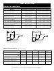
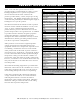
Specifications

INSTALLATION
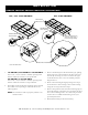
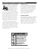
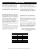
REMOTE CONTROL HOUSING MOUNTING INSTRUCTIONS
PAN DIVIDER
BARS #16019
FLEXIBLE WATER-
TIGHT TETHER
Apply a food grade silicone
along the outside edge of
the hot well support flange.
FLEXIBLE WATER-
TIGHT TETHER
DECOR FACE SCREWS
1. 100-HW/HWLF, 200-HW/HWLF or 300-HW/HWLF:
Cut a 5-1/4" x 4-1/2" (133mm x 114mm) opening in the
location where the control is to be positioned.
400-HW/HWLF or 500-HW/ HWLF:
Cut a 9-1/8" x 4-1/2" (232mm x 114mm) opening in the
location where the control is to be positioned.
2. Thoroughly clean and dry the mounting surface around
the control cut-out opening on which the décor face
will be applied.
NOTE: The control face will not properly adhere to an
unclean surface.
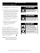
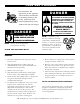
3. Remove the knob(s) from the thermostat(s) by pulling
knob away from control. Remove the décor face from
the unit by removing one screw located to the right
of the thermostat. (Two screws for double pod.) See
diagram above.
4. Route control housing through opening cut in step 1.
Secure the décor face housing to the control housing
using the screw(s) removed in step 3.
5. Remove the protective film from the mounting tape on
the inside flanges of the décor face and apply the décor
face to the mounting surface. Two holes are provided
in décor face for additional mounting screws (not
provided) if desired.
6. Reattach the knob(s) to the thermostat(s).
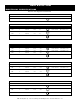
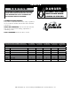
100-, 200- & 300-HW/HWLF* 400- & 500-HW/HWLF*
* shown with hw flange