INTERFACES MANUAL PART NUMBER: 400-0062-003 PRODUCT REVISION: 2 VA6835FC SYSTEM UNIVERSAL INTERFACE USER’S GUIDE
INTERFACES INTRODUCTION TABLE OF CONTENTS Page Altinex appreciates your purchase of the VA6835FC Analog Interface. We are certain that you will find it reliable and simple to use. PRECAUTIONS / SAFETY WARNINGS ...............2 GENERAL ................................ .......................... 2 RACK MOUNT SAFETY GUIDELINES ..............2 INSTALLATION................................ ..................2 CLEANING................................ ......................... 2 FCC / CE NOTICE .................
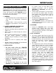
INTERFACES PRECAUTIONS / SAFETY WARNINGS 1 Please read this manual carefully before using your VA6835FC Interface. Keep this manual handy for future reference. These safety instructions are to ensure the long life of your VA6835FC and to prevent fire and shock hazard. Please read them carefully and heed all warnings. • 1.1 GENERAL • • • Unauthorized personnel shall not open the unit since there are high-voltage components inside.
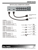
INTERFACES • Main Video Output Connector Compatibility Any changes or modifications to the unit not expressly approved by Altinex, Inc. could void the user’s authority to operate the equipment. ABOUT YOUR INTERFACE 2 There are varieties of computers and computer video cards on the market today. There are also several data monitors and large screen data projectors.
INTERFACES Horizontal Position Range Cross-talk Power Internal Power Supply Power Consumption Table 3.
INTERFACES 5
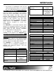
INTERFACES designated Altinex adapter cables, such as VGA, MAC, SUN, SGI, or RGB. The VA6835FC has two key functions. It’s first function is to amplify or buffer the signal to insure that it is strong enough to travel distances of 100 ft or farther through a coaxial cable. The second function is to process the sync and to convert it to a format that is acceptable to several displays. PIN No. 1 2 3 4 5 6 7 8 9 10 11 12 13 14 15 4.
INTERFACES CONNECTOR Red Green Blue Sync Hor. Vertical the power input connector displays the proper voltage. To change the setting, unplug the VA6835FC, and squeeze the clips on either side of the fuse box. Pull out the fuse holder and turn it 180 degrees, resetting it with the proper voltage shown through the window. Re-insert the fuse box making sure that the side clips of the fuse box lock securely into place.
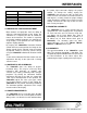
INTERFACES APPLICATION DIAGRAM 5 INSTALLING YOUR INTERFACE 6 Step 5. Connect one end of a BNC cable to output one or two of the VA6835FC units. Connect the other end to the RGB input on the projector or monitor. Usually either a 4 BNC or 5 BNC coaxial cable is used, depending on whether display devices require composite sync or horizontal and vertical sync signals. Step 1.
INTERFACES OPERATION This is used primarily when interfacing to laptop computers to imitate the presence of a local monitor. Typically, this recognition will take place during the boot up stage of a computer. If your computer does not output video, place the ID Bit switch in the ON position and reboot the computer. When in the OFF position, the ID Bit will be passed through the local monitor output port. 7 According to Table 4, the settings of the VA6835FC Interface can be adjusted using dipswitches.
INTERFACES ACCESSORIES Model No.
INTERFACES use the “HV OUT” dip-switch? 200 ft, 5 BNC M to 5 BNC M CB5100PL5BM02005BM 250 ft, 5 BNC M to 5 BNC M CB5100PL5BM02505BM All MS81 series cables listed above are 3 ft. long. These cables are also available in 6 ft. and 12 ft. lengths. Please call 1-714-990-2300 for a wider selection of cables.
INTERFACES TROUBLESHOOTING GUIDE 1. When the correct voltage is applied to the Interface, the power LED should be ON. 2. The “Termination” dip-switch should be in the ON position if a Y cable (breakout) is not used on the input. 3. Make sure the cables have the correct pinouts and the connection and quality of the cables are good. 4. Make sure that the source and display are scan-rate compatible. The projector should support an appropriate signal format (RGsB, RGBS or RGBHV).