INTERFACES MANUAL PART NUMBER: 400-0103-001 PRODUCT REVISION: 2 VA6822 SYSTEM INTERFACE WITH AUDIO & EQUALIZATION USER’S GUIDE
INTERFACES TABLE OF CONTENTS Page PRECAUTIONS / SAFETY WARNINGS ............... 2 GENERAL.......................................................... 2 RACK MOUNT SAFETY GUIDELINES.............. 2 INSTALLATION ................................................. 2 CLEANING ........................................................ 2 FCC / CE NOTICE ............................................. 2 ABOUT YOUR INTERFACE ................................. 3 TECHNICAL SPECIFICATIONS ...........................
INTERFACES 1 • Please read this manual carefully before using your VA6822 Interface. Keep this manual handy for future reference. These safety instructions are to ensure the long life of your VA6822 and to prevent fire and shock hazard. Please read them carefully and heed all warnings. Do not place heavy objects on top of the VA6822. If the VA6822 is to be mounted to a table or wall, use only ALTINEX-made mounting accessories like brackets (DA1293FC or DA1294FC) and cables for optimum setup.
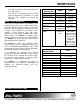
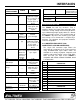
INTERFACES user will be required to correct the interference at his own expense. • FEATURES/ DESCRIPTION GENERAL No. of Inputs Input Connector Any changes or modifications to the unit not expressly approved by ALTINEX, Inc. could void the user’s authority to operate the equipment. ABOUT YOUR INTERFACE VIDEO 1 1 3.5 mm stereo 15-pin HD jack Female 1 Main + 1 1 Main + 1 Local No. of Outputs Local Monitor Monitor Local Output 3.
INTERFACES ELECTRICAL AUDIO SPECIFICATIONS Input Signals Level 0.1 to 4.8V p-p Impedance Output Signals Type Level 10k Ohms Balanced on Main; Unbalanced on Local 0.1 to 4.8V p-p Position Range VIDEO Panel, 10% through remote Hposition connector Power Power Input 100-240V AC, 50/60Hz, 0.4A Power 10 watts max. Consumption Table 3. VA6822 Electrical Specifications 0.3 to 1.2V p-p for RGB video signal TTL (+/-) for H, V, or C sync signal. 0.
INTERFACES offers the main output with 5-BNC connectors. By connecting to the appropriate connectors of the VA6822, it can provide RGSB, RGBHV, or RGBS output signals. Horizontal Sync 13 Vertical Sync 14 SCL – DDC Clock 15 Table 4. VA6822 Input pin-outs With these connectors the VA6822 can be connected to compatible data projectors using 3 coax, 4 coax, or 5 coax cables. 4.2 LOCAL MONITOR OUTPUT (15-PIN HD CONNECTOR) The 15-Pin HD connector output is used to connect the local monitor to the interface.
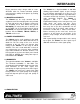
INTERFACES Please note that using a longer cable or a nonALTINEX cable for remote horizontal position could affect the stability of the picture by creating unwanted jitter. The VA6822 has a high bandwidth of 350 MHz allowing high-resolution signals to pass through the unit without attenuation for a long run. For cable runs longer than 100ft, the signal attenuates at medium and/or high frequency.
INTERFACES DESCRIPTION OF VA6822 4 7 7
INTERFACES APPLICATION DIAGRAM 5 8 8
INTERFACES INSTALLING YOUR INTERFACE to 240 VAC 50/60Hz. It is not necessary to change any voltage selection settings on the VA6822. The LED on the front and back panel of the VA6822 will light GREEN if the appropriate input signal is present and will remain RED if a valid input is not detected. 6 Step 1. Please attach the VA6822 Interface on the rack using the provided rack mount hardware or on/under furniture using the optional TM Series ALTINEX brackets. Step 2.
INTERFACES OPERATION 7.4 SYNC ON GREEN SWITCH 7 Often systems that use large matrix switchers are designed to switch signals in RGsB format. This is done to reduce the cost of the switcher and cable. In these types of systems, the ability of the VA6822 to output Sync on Green can be very helpful. It is important to note that the VA6822 will not separate the Sync signal from the Green video signal if the input signal is RGsB.
INTERFACES ACCESSORIES MS8123CA/ MS8153CA/ MS8163CA MS8124CA/ MS8154CA/ MS8164CA RGB MS8129CA AUDIO CABLE 8 Model No.
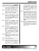
INTERFACES FREQUENTLY ASKED QUESTIONS No: 1 2 3 4 Question When and why do I need to use the horizontal position dial? What dipswitch do I set to receive composite SYNC output? When and why would I use the Sync on Green dipswitch, although the unit does not separate Sync from Green? When do I use the H&V Out dip-switch? 9 TROUBLESHOOTING GUIDE Answer The horizontal position control dial enables or disables the control of the horizontal position of the image.
INTERFACES ALTINEX POLICY returned without an RMA number may experience a delay in service. 11 11.1 LIMITED WARRANTY If your product is out of warranty and needs service, contact the ALTINEX Sales Department for an RMA (Return Material Authorization). Products returned without an RMA number may experience a delay in service. The service charges will be quoted to you before the actual repairs are done.