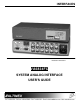
INTERFACES MANUAL PART NUMBER: 400-0039-003 PRODUCT REVISION: 1 VA6834FC SYSTEM ANALOG INTERFACE USER’S GUIDE
INTERFACES INTRODUCTION TABLE OF CONTENTS Page Altinex appreciates your purchase of the VA6834FC Analog Interface. We are sure you will find it to be reliable and simple to use. PRECAUTIONS / SAFETY WARNINGS ...............2 GENERAL ..........................................................2 RACK MOUNT SAFETY GUIDELINES ..............2 CLEANING .........................................................2 FCC / CE NOTICE .............................................
INTERFACES PRECAUTIONS / SAFETY WARNINGS 1 Please read this manual carefully before using your VA6834FC Interface. Keep this manual handy for future reference. These safety instructions are to ensure the long life of your VA6834FC and to prevent fire and shock hazard. Please read them carefully and heed all warnings. • 1.1 GENERAL • • • Unauthorized personnel shall not open the unit since there are high-voltage components inside.
INTERFACES • Any changes or modifications to the unit not expressly approved by Altinex, Inc. could void the user’s authority to operate the equipment. ABOUT YOUR INTERFACE MECHANICAL VA6834FC Width (inches) 8.50in Height (inches) 1.75in Depth (inches) 4.93in. Weight (pounds) 2.0lbs. Ship Weight (pounds) 2.8lbs. Material 0.1" Aluminum Finish Gray Faceplate Lexan T° Operating 10°C-35°C T° Maximum 50°C Humidity l 90% non-condensing MTBF (calculations) 40,000 hrs Table 2.
INTERFACES VA6834FC DESCRIPTION types of local monitors using designated Altinex adapter cables such as VGA, MAC, SUN, SGI or RGB. 4 The VA6834FC has two key functions. Its first function is to buffer the signal and insure that it is strong enough to travel a distance of 100 ft or longer through a coaxial cable. The second function is to process the sync and to convert it into a format that is acceptable to most displays. PIN No. 1 2 3 4 5 6 7 8 9 10 11 12 13 14 15 4.
INTERFACES 5
INTERFACES 6
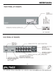
INTERFACES CONNECTOR Red Green Blue Sync Hor. Vert. 4.6 POWER REQUIREMENTS MAIN DUAL OUTPUT (6-BNC FEMALE) Red Video Green Video Blue Video Composite Sync/ Horizontal Horizontal Sync Vertical Sync The VA6834FC may be used with either 120V or 220V throughout the world for ease of use. Always make sure that the fuse box window above the power input connector displays the proper voltage. To change the setting, unplug the VA6834FC, and squeeze the clips on either side of the fuse box.
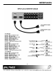
INTERFACES APPLICATION DIAGRAM 5 INSTALLING YOUR INTERFACE 6 Step 1. Please attach the Interface on the rack using the provided rack mount hardware. The Interface can also be attached on top or under furniture using the optional TM Series Altinex brackets. Step 2. Before you plug in the power cord to the unit, please verify that the voltage rating of 110V/220V which is located on the FUSE CLIP at the rear of the unit is the same as the power outlet.
INTERFACES OPERATION the boot up stage of the computer. If your computer does not output video, place the I.D. Bit switch in the ON position and reboot the computer. When in the OFF position, the ID Bit will be passed through the Local Monitor Output port. 7 The settings of the VA6834FC Interface can be adjusted using the dip-switches in Table 4. There are no other adjustments necessary to operate the unit.
INTERFACES ACCESSORIES Model No. DA1293SX DA1294SX TM1271 TM1272 TM1273 Model No.
INTERFACES 100 ft, 5-BNC M to 5-BNC M CB5100PL5BM01005BM 150 ft, 5-BNC M to 5-BNC M CB5100PL5BM01505BM 200 ft, 5-BNC M to 5-BNC M CB5100PL5BM02005BM 250 ft, 5-BNC M to 5-BNC M CB5100PL5BM02505BM All MS81 series cables listed on the previous page are 3 ft. long. These are available in 6 ft. and 12 ft. lengths. Please call 1-714-990-2300 for a wider selection of cables.
INTERFACES TROUBLESHOOTING GUIDE PIN MAC VGA SUN No. n/a n/a Red A1 n/a n/a Green A2 n/a n/a Blue A3 Red Gnd Red N/C 1 Red Green N/C 2 C.Sync Blue Sense 3 ID Bit 01 ID Bit Sense Rtn 4 Green N/C C. Sync Sens 5 Green Gnd. Red Rtn. N/C 6 ID Bit 02 Green Rtn. N/C 7 N/C Blue Rtn. N/C 8 Blue N/C N/C 9 ID Bit 03 Gnd N/C 10 C/V Gnd. ID Bit 11 V. Sync ID Bit 12 Blue Gnd. H. Sync. 13 H. Gnd V. Sync 14 H. Sync N/C 15 Table 7. Common Computer Video Cards pin-out. 12 10 1.
INTERFACES ALTINEX POLICY If your product is out of warranty and needs service, contact the Altinex Sales Department for an RMA (Return Material Authorization). Products returned without an RMA number may experience a delay in service. The service charges will be quoted to you before the actual repairs are done. 11 11.1 LIMITED WARRANTY Altinex warrants that its products and cables are free from defects in materials under normal use and service.