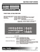
MATRIX SWITCHERS MANUAL PART NUMBER: 400-0047-004 PRODUCT REVISION: 2 MAX SERIES MATRIX SWITCHERS USER’S GUIDE
MATRIX SWITCHERS INTRODUCTION TABLE OF CONTENTS Page Altinex appreciates your purchase of the MAX Series Matrix Switcher. We are sure you will find it a reliable and useful product. PRECAUTIONS/SAFETY WARNINGS..................2 GENERAL ..........................................................2 Superior performance for the right price backed by solid technical and customer support is what we have to offer. INSTALLATION ..................................................2 RACK-MOUNT INSTALLATION .......
MATRIX SWITCHERS PRECAUTIONS/SAFETY WARNINGS hazardous conditions may be created by an uneven weight distribution. Allow 1-U of rack space for every four MAX Switcher modules for air circulation. This will reduce heat build up and will prolong the life of the MAX Switcher. 1 Please read this manual carefully before using your MAX Series Matrix Switcher. Keep this manual handy for future reference.
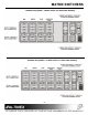
MATRIX SWITCHERS ABOUT YOUR MAX SERIES MATRIX SWITCHER Height (inches) Width (inches) Length (inches) Weight (pounds) 2 The Altinex MAX Series Matrix Switchers are designed to route multiple computers or video sources to multiple display devices in a wide range of audio/visual installations.
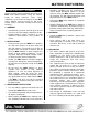
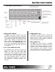
MATRIX SWITCHERS Power Cord 5-position Terminal Connector 4-position Terminal Connector x x x DIAGRAM OF FRONT/BACK PANEL 4 4
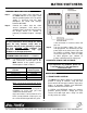
MATRIX SWITCHERS 4.3 AUDIO PORTS (L&R) 4.1 BACK PANEL CONTROL The MAX Series Matrix Switcher is available with either mono or stereo balanced audio inputs and outputs for clear quality sound. The terminal block connectors used for Audio simplify the connection of the Audio signal. The MAX Series Matrix Switcher offers great flexibility in configuring the switcher. Each portion of the signal can be controlled independently or in any desired grouping.
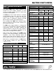
MATRIX SWITCHERS The computer video signal can be RGsB, RGBS, or RGBHV format. The broadcast video signal can be C-Video, S-Video, or Component Video in NTSC, PAL or SECAM standard. The audio signal can be Mono or Stereo. Depending on the signal and size configuration of the MAX Switcher, the back panel of the switchers will be different. Here are examples of an 8x4 MAX switcher for different number of signals.
MATRIX SWITCHERS 7
MATRIX SWITCHERS 8
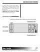
MATRIX SWITCHERS INSTALLING YOUR SWITCHER Step 1. Step 2. 6 Connect the power entry connector of the MAX Switcher to the power outlet with the provided power cord. The power supply is universal and will work throughout the world with voltages between 90V-260V. Connect the cables from the video sources (computers, VCR, others) to available inputs 1 through 8 and connect the display device (i.e. monitor or projector) to available outputs 1 through 4.
MATRIX SWITCHERS In PRESS and HOLD mode the switcher performs secondary functions. Press and hold the button until all LED’s flash and the unit beeps a second time. For example, to display the signal from a source connected to input 3 on the monitors and connected to outputs 1 and 3 press: INPUT3 + OUTPUT1 & INPUT3 + OUTPUT3 or OUTPUT1 + INPUT3 & OUTPUT3 + INPUT3 In POWER-ON mode the switcher changes settings that are stored in the switcher’s memory.
MATRIX SWITCHERS Press and hold Input 5 and turn the power ON. Then wait for long and short beep to set the No sync delay function. Press and hold Output 4 and turn power ON, then wait for long and short beep to set the unit ID to 4. Press and hold Input 6 and turn the power ON. Then wait for long and short beep to set a 5second sync delay. RECALL PRE-SET MEMORY If any connection configuration of inputs to outputs is stored into the switcher’s memory, it can be recalled using this option.
MATRIX SWITCHERS command is not recognized an [ERR] string will be returned. RESET To reset the switcher to its factory default setting, press [VIDEO] and hold it until all LED’s flash. 1. SQUARE BRACKETS ARE PART OF THE COMMAND. 2. USE UPPERCASE LETTERS FOR ALL COMMANDS. 3. PLEASE PUT A 50 ms DELAY BETWEEN TWO CONSECUTIVE COMMANDS. When the switcher is reset: - Baud rate is changed to 2400 bps. - Unit ID is selected to 1. - IR-Control mode is disabled. - Sync Delay is set to None.
MATRIX SWITCHERS work. Once programmed this setting remains in effect even after power is turned on or off. This command is used for programming the switcher. It should not be used as a part of a program to operate the switcher. The [SETIDn] command is used for programming the switcher; it should not be used as a part of a program to operate the switcher.
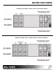
MATRIX SWITCHERS 1. The number of outputs must be the same on all units to be looped. 2. Output offset is zero for all units. 3. The input offset must be set for all units except for the first one. The offset for the input should be the same as the last number of the previous unit 4. The number of inputs available on the second unit for a direct connection is the difference between the maximum number of inputs of the second unit, and the number of looped outputs.
MATRIX SWITCHERS command actions are lost if power to the unit is lost or if the unit is reset in any way. [RSET] This command resets or initializes the switcher to the power-on condition. With this command, the baud rate is changed to 2400 bps, all current inputs from outputs are disconnected, unit ID number is set to 1, memory number 1 is recalled, and all levels (VIDEO & AUDIO) are enabled.
MATRIX SWITCHERS This command allows control of each signal level independently. Once issued it is active until another [SELn] command is issued or the front panel is used to control the switcher. mm- output number 01 to 04 P - path This command sets the switching path of connecting an input to an output but does not switch. When the front panel is used, the levels to be controlled are defined by the front panel selections.
MATRIX SWITCHERS This command is used to select multiple inputs and multiple outputs without switching and then switch them together with a single command. This is a very useful command for scene or salvo switching or for controlling through a PC. inputs and outputs of the specific MAX Switcher without sending four different commands with 50 ms delays between each command.
MATRIX SWITCHERS connection between inputs and outputs for active channels of a switcher with a selected unit ID number. [SWUx] command will delay switching for that period. [FDBKn] n- 1 enable feedback [OK] or [ERR] Memory saved in location no.1 is recalled, when the MAX Switcher is powered up or RESET. If [Sel7] saves the memory location for the audio channel, then the switcher will only recall input to output connection for those audio channels only.
MATRIX SWITCHERS 7.6 IR-CONTROL MODE 5. Wired Infra-red Receiver Step 1. Make sure that the MAX Switcher is in the OFF position. Step 2. Plug the 4-position terminal plug located at the end of the cable into RS-232 Port 1 located on the top-right corner on the backside of the switcher. Note: Inserting the 4-positon Terminal connector on RS-232 port 2 will damage the receiver. Step 3. Please put the receiver within a range of the transmitter and within 30° angle for optimum operation.
MATRIX SWITCHERS CABLES AND ACCESSORIES Model No. 8 controlled from the front panel.
MATRIX SWITCHERS 8 9 10 Can I use contact closure to control the switcher? Is the MAX Series capable of controlling various projectors? How can I prevent an end user from tinkering with the controls? commands being sent. Also make sure that all commands have a square bracket ‘[‘ before and “]” after each command if the code is set to 1. port simultaneously.
MATRIX SWITCHERS ALTINEX POLICY If your product is out of warranty and needs service, contact the Altinex Sales Department for an RMA (Return Material Authorization). Products returned without an RMA number may experience a delay in service. The service charges will be quoted to you before the actual repairs are done. 11 11.1 LIMITED WARRANTY Altinex warrants that its MAX Series Matrix Switchers are free from defects in materials under normal use and service.