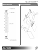
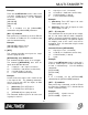
MULTI-TASKER™ MANUAL PART NUMBER: 400-0177-002 MT104-108 6-IN, 1-OUT S-VIDEO SWITCHER CARD FOR MULTI-TASKER™ ENCLOSURES USER’S GUIDE
MULTI-TASKER™ TABLE OF CONTENTS Page PRECAUTIONS / SAFETY WARNINGS.............. 2 1.1 GENERAL ................................ ................. 2 1.2 INSTALLATION................................ ......... 2 1.3 CLEANING ................................ ................ 2 1.4 FCC / CE NOTICE................................ ..... 2 ABOUT YOUR MULTI-TASKER™....................... 3 TECHNICAL SPECIFICATION ............................ 3 PRODUCT DESCRIPTION................................ ..
MULTI-TASKER™ PRECAUTIONS / SAFETY WARNINGS 1 • This equipment has been tested and found to comply with the limits for a Class A digital device, pursuant to Part 15 of the FCC Rules. These limits are designed to provide reasonable protection against harmful interference when the equipment is operated in a commercial environment.
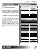
MULTI-TASKER™ ABOUT YOUR MULTI-TASKER™ 2 TECHNICAL SPECIFICATION MT104-108 6-in 1-out S-Video Switcher Card 3 FEATURES/DESCRIPTION MT104-108 GENERAL Inputs (6) 4-pin Mini DIN External Input Connectors Connectors (1) 10-pin IDC Internal Input Connector Connector Outputs (1) (1) 4-pin Mini DIN Output Connector Connector Approvals CE/FCC Table 1. MT104-108 General MECHANICAL MT104-108 Enclosure Slots Req'd One Weight 0.43lb (0.19kg) Shipping Weight 1 lb. (0.
MULTI-TASKER™ PRODUCT DESCRIPTION 4 APPLICATION DIAGRAM 4 5
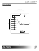
MULTI-TASKER™ Diagram 2: Block Diagram MT104-108 6-IN 1-OUT S-VIDEO SWITCHER (4-PIN MINI DIN CONNECTORS IN/OUT) EXPANSION 7 POWER 1 2 3 OUT IN 4 5 6 INPUT SELECT OUTPUT ON/OFF CONTROL 5
MULTI-TASKER™ INSTALLING YOUR MULTI-TASKER™ Commands not ending in "S" will still be executed but will not be restored when the system is reset (power off & power on again). 6 Step 1. Slide the MT104-108 into an available slot in the Multi-Tasker™ Enclosure in order to connect to the bus. Make sure that the MT104-108 card fits into place. Secure the card to the Multi-Tasker™ by tightening the retainer screws located on the top and bottom of the MT104-108 card. 7.
MULTI-TASKER™ Example: [ONmCnUiS]: for a SINGLE card One MT104-108 card is in slot #2 of unit 3: Send the command [VERC2U3] and the Multi-Tasker™ Enclosure will return: This command enables input “m” and disables all other inputs. MT104-108 690-0160-002 Default when plugged in = Input 1 is ON MT104-108 = card type 690-0160-002= software version m = Input number (m = 1 to 7, 7 is internal) [ONmCnUi]: enables input This command receives the status of the card.
MULTI-TASKER™ m Cn Ui S Example: There are two MT104-108 cards in slots 6 and 7 of unit 3. Enable input 1 of card 6 and input 3 of card 7 simultaneously. Use the following commands: Example: 1) [ON1C6U3P] [ON3C7U3P] [SW] 2) [OFF…..P]: sets path This command will set the path for the output, but it is not active until the switch command, [SW], is executed. Commands ending in "P" are not executed immediately. The path for outputs on multiple cards or the same card can be preloaded.
MULTI-TASKER™ commands along with a brief description will be displayed in the Terminal Window 6. […S] – Save This command will save the configuration command being sent in memory. When sending the command [ON1C4S], after reset or power up, output 1 on C4 will be enabled. 11. [WR] This command groups multiple cards in the Enclosure. Each unit contains a maximum of nine groups. 7.
MULTI-TASKER™ [G1]: will return feedback as ON12 G1U0. [G2]: will return feedback as ON2 G2U0. 7.3 SUMMARY OF COMMANDS 1) [VER] Receives software version 2) [Ci] Receives status of the card 3) [CiS] Saves card configuration 4) [ON] Turns on one or more outputs for a single card or a group of cards 5) [OFF] Turns off one or more outputs for a single card or a group of cards Example: 6) […S] Save the command configuration The cards in slots 1, 2 and 19 are part of group 5 in unit 1.
MULTI-TASKER™ TROUBLESHOOTING GUIDE Cause 3: Cable connections are incorrect. 8 Solution: We have carefully tested and have found no problems in the supplied MT104-108; however, we would like to offer suggestions for the following: 8.1 LED IS NOT LIT Make sure that cables are properly connected. Also, make sure that the continuity and wiring are good. If there is still no display present, see Cause 4. Cause 1: Card cage is not plugged in. Cause 4: The display has a problem.