
User`s guide

MT115
MT115MT115
MT115-
--
-110 Video+Audio Dual TP Transmitter
110 Video+Audio Dual TP Transmitter110 Video+Audio Dual TP Transmitter
110 Video+Audio Dual TP Transmitter
User’s Gui
User’s GuiUser’s Gui
User’s Guide
dede
de
400-0433-006
1
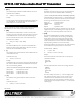
EQ1
HW
SW
EQ2
HW
SW
HW
SW
GAIN
HW
SW
GAIN
SW3
SW5
SW6
SW4
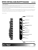
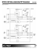
Input 1
Equalization and Gain
SW=Software
HW=Hardware
HW=Hardware Control
SW=Software Control
Equalization and Gain
Input 2
Welcome!
We greatly appreciate your purchase of the MT115-110 Output Expansion
Card. We are sure you will find it reliable and simple to use. Superior
performance for the right price, backed by solid technical and customer
support is what ALTINEX has to offer.
We are committed to providing our customers with
Signal Management Solutions
®
to the most demanding audiovisual
installations at very competitive pricing and we welcome you to join the
ranks of our many satisfied customers throughout the world.
1. Precautions and Safety Warnings
Please read this manual carefully before using your MT115-110 and keep it
handy for future reference. These safety instructions are to ensure the long
life of your MT115-110 and to prevent fire and shock hazards. Please read
them carefully and heed all warnings.
1.1 General
• Qualified ALTINEX service personnel or its authorized
representatives must perform all service.
1.2 Handling
• Handle the MT115-110 carefully. Dropping or jarring can damage the
card.
• The MT115-110 contains components that are sensitive to
electrostatic discharge (ESD). Always use ESD safety precautions
when touching the card.
• To prevent fire or shock, do not expose this unit to water or moisture.
Do not place the MT115-110 in direct sunlight, near heaters or
heat-radiating appliances, or near any liquid. Exposure to direct
sunlight, smoke, or steam can harm internal components.
• Do not pull any cables that are attached to the MT115-110.
1.4 Cleaning
• Clean only the connector area with a dry cloth. Never use strong
detergents or solvents such as alcohol or thinner. Do not use a wet
cloth or water to clean the card. Do not clean or touch any
component or PCB.
1.5 FCC Notice
• This device complies with Part 15 of the FCC Rules. Operation is
subject to the following two conditions: (1) This device may not cause
harmful interference, and (2) this device must accept any interference
received, including interference that may cause undesired operation.
• This equipment has been tested and found to comply with the limits
for a Class A digital device pursuant to Part 15 of the FCC Rules.
These limits are designed to provide reasonable protection against
harmful interference when the equipment is operated in a
commercial environment. This equipment generates, uses, and can
radiate radio frequency energy and if not installed and used in
accordance with the instructions found herein, may cause harmful
interference to radio communications. Operation of this equipment in
a residential area is likely to cause harmful interference in which case
the user will be required to correct the interference at his expense.
• Any changes or modifications to the unit not expressly approved by
ALTINEX, Inc. could void the user’s authority to operate the
equipment.
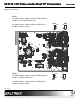
2. Installation Procedures
Step 1. Determine the switch settings as shown or use Diagram 3 of the online user's guide. Software video
gain adjustment is available with RS-232 control, or select hardware for a fixed gain of one.
See the online user's guide for RS-232 command details for gain and equalization control.
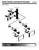
Step 2. Turn off power to the MultiTasker system and disconnect from AC power.
Step 3. Remove a slot cover (MT200-101) from one of the unused slots. Identify the slot number and note that
it is for RS-232 control.
Step 4. Slide the MT115-110 into the enclosure in order to connect it to the bus. Make sure the card fits into
place and then secure the card by tightening its retainer screws.
Step 5. Restore power to the enclosure. The LEDs for each input should be on and red.
Step 6. Connect the computer/component video and audio sources to Inputs 1 and 2. If a properly formatted
input signal is available, the Input LED will turn green.
Step 7. Connect the 4TP outputs to the input of the 4TP receivers.
Step 8. The MT115-110 is now ready for operation.
Note: Video equalization is provided to fine-tune the displayed image on the remote display. Equalization
adjustments on the transmitter and receiver work together. Start with both set to minimum (fully
CCW) and adjust slowly while monitoring the remote image. Make the most precise adjustments on
the receiver end closest to the video display.
3. Limited Warranty/Return policies
Please see the ALTINEX website at www.altinex.com for details on warranty and return policies.