MULTITASKER® MANUAL PART NUMBER: 400-0443-004 MT115-111 DUAL TWISTED PAIR RECEIVER TO COMPUTER/COMPONENT VIDEO + AUDIO, USER’S GUIDE
MULTITASKER TABLE OF CONTENTS Page PRECAUTIONS / SAFETY WARNINGS................ 2 GENERAL..........................................................2 HANDLING ........................................................2 CLEANING.........................................................2 FCC NOTICE .....................................................2 ABOUT YOUR MT115-111....................................... 3 TECHNICAL SPECIFICATIONS.............................. 3 PRODUCT DESCRIPTION .......................
MULTITASKER PRECAUTIONS / SAFETY WARNINGS • 1 Please read this manual carefully before using your MT115-111 and keep it handy for future reference. These safety instructions are to ensure the long life of your MT115-111 and to prevent fire and shock hazards. Please read them carefully and heed all warnings. 1.1 GENERAL • Qualified ALTINEX service personnel or its authorized representatives must perform all service. 1.2 HANDLING • • • • Handle the MT115-111 carefully.
MULTITASKER ABOUT YOUR MT115-111 2 TECHNICAL SPECIFICATIONS Specifications are subject to change. See www.altinex.com for up-to-date information. MT115-111 Dual Twisted Pair Receiver to Computer/Component Video+ Audio, FEATURES/ DESCRIPTION The MT115-111 provides a means of receiving computer or component video and audio signals over Twisted Pair-type (CAT-5) cable when used together with an ALTINEX Twisted Pair Video Transmitter, such as the MT115-110 or TP115-110.
MULTITASKER ELECTRICAL MT115-111 Input Signal CAT-5/6 Twisted Pair Video/Sync/Audio Signals ALTINEX Standard Audio Output Signal Gain 0 dB +/- 0.5 dB Level 1.0 Vp-p max Video Output Signal Video Signal 1.0 Vp-p max Video Impedance 75 ohm SYNC Signal TTL (+/-) Video Resolutions VGA through UXGA 480p through 1080i Power (from enclosure) +6V 0.600 A (3.6 W) -6V 0.350 A (2.1 W) Total Power Consumption 5.7 W max. Table 3.
MULTITASKER PRODUCT DESCRIPTION 400-0443-004 4 5
MULTITASKER APPLICATION DIAGRAMS 5 DIAGRAM 1: TYPICAL SETUP MT115-111 TP115-110 TP115-110 400-0443-004 6
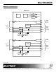
MULTITASKER DIAGRAM 2: INTERNAL VIEW MT115-111 PS CH1 SIGNAL DETECT POWER CH2 SIGNAL DETECT POWER MP L PAIR 4 R INPUT 1 4TP RJ-45 SYNC SEPARATOR V PAIR 2 H R/Pr PAIR 3 B/Pb PAIR 1 G/Y S/W EQ EQ L R SYNC SEPARATOR PAIR 2 PAIR 3 B/Pb PAIR 1 G/Y EQ 400-0443-004 H/W EQ 7 MONO AUDIO 3.5 mm V H R/Pr S/W RGBHV YPbPr VIDEO 15-PIN HD H/W PAIR 4 INPUT 2 4TP RJ-45 MONO AUDIO 3.
MULTITASKER DIAGRAM 3: SWITCH SETTINGS SW8 GAIN2 GAIN1 EQ2 EQ1 SW7 400-0443-004 SW6 SW3 SOG1 SOG2 SW4 SW1 CONTROL OUTPUT CONTROL DESCRIPTION Video Gain 1 2 Set SW6 to SW for software or HW for a fixed gain = 1. Set SW8 to SW for software or HW for a fixed gain = 1. Equalization 1 2 Set SW4 to SW for software or HW for hardware. Set SW2 to SW for software or HW for hardware. Sync-on-Green 1 2 Set SW3 to ON for a Sync-on-Green output. Set SW1 to ON for a Sync-on-Green output.
MULTITASKER INSTALLING YOUR MT115-111 6 OPERATION Step 1. Determine the appropriate switch settings using DIAGRAM 3 on page 8. 7.1 RS-232 CONTROL The MT115-111 has many advanced remote-control capabilities accessible through standard RS-232 communication. Control may be accomplished through a computer, control system, or any device capable of RS-232 communication. Step 2. Turn off power to the MultiTasker system and disconnect from AC power. Step 3. Remove an unused slot cover (MT200-101).
MULTITASKER 7.2 DESCRIPTION OF COMMANDS Each command consists of three Function, Card ID, and Unit ID. [ Function , Card ID , Unit ID ] COMMAND ORGANIZATION parts: The RS-232 commands in this section are organized into the following 5 categories: Basic Commands Feedback Control Card Control Card IDs Groups Example: [VERC3U2] VER C3 U2 = Function = Card ID or Group ID = Unit ID (optional for Unit ID 0) For Function, see a detailed explanation under each command description.
MULTITASKER 2. [C] 5. [CLR] This command receives the status of the card. Cn = Card ID (n = # from 1 to max slots) This command clears the card settings and returns it to the factory default values. The defaults gain setting is 4 and the default equalization setting is 32 for each input. Example: Command Format: [CLRCn] There is one MT115-111 card in slot 4.
MULTITASKER 10. [?C] FEEDBACK CONTROL The next commands are a function of both the card and the front panel and allow flexibility over when and how card information is displayed. This command will return general information about the card and its status. 8. [FBD] Cn = Card ID (n = # from 1 to max slots) Command Format: [?Cn] This command turns feedback delay on or off. It is necessary when installing some newer cards in older systems.
MULTITASKER Feedback Prefix Definitions: MT Card Model Number VR Firmware Revision GN Video Gain Levels EQ Equalization Levels CARD CONTROL Example: 14. [EQ=] Command = Feedback = Card control commands allow the main functions of the card to be executed over the RS-232 bus, or from the front panel’s programmable keys. This command sets the equalization for an input to a value specified by the user.
MULTITASKER 16. [GAIN=] 17. [RSI] This command sets the gain level for an input to a value specified by the user. A gain setting of 4 is equivalent to unity gain. This command resets the card IDs in the system. After sending this command, each card ID in the system will match the slot number of the card. If the card is moved to another slot, its ID number will be the new slot number.
MULTITASKER 20. [SID+] GROUP COMMANDS This command sets the card ID of all cards in a system to their slot number plus the offset value. Group commands allow several cards with the same functions to be controlled simultaneously with a single command. Up to 8 groups (G1-G8) may be defined. These commands apply to all cards, not only the MT115-111.
MULTITASKER 24. [RMG] 7.3 SUMMARY OF COMMANDS This command deletes one or all groups. Basic Commands Command Format: [RMGk] 1) [VER] Display firmware version Gk = Group ID (k = # from 1-8, * for all) 2) [C] Display card status Example: 3) [CnS] Save card settings Remove all cards from G52 by sending [RMG5]. The system will return the following feedback: 4) [..
MULTITASKER 7.4 MENU MODE Menu Mode commands allow virtually the same functionality as programming commands. Unlike the programming commands in the previous sections, menu commands prompt the user to select from a list of available options. The system then responds based upon selections made by the user. 4. Enter the ID number of the desired system. In the example above, enter a “1” for the MultiTasker with unit ID 1. 5.
MULTITASKER 2: GAIN CONTROL GAIN CONTROL 1: INPUT#1 4 GAIN CONTROL INPUT#1 (4) 1: INCREASE GAIN LEVEL 2: DECREASE GAIN LEVEL 2: INPUT#2 4 GAIN CONTROL INPUT#2 (4) 1: INCREASE GAIN LEVEL 2: DECREASE GAIN LEVEL 3: SAVE CONFIGURATION SAVE CURRENT CONFIGURATION? 1: YES 2: NO 4: RESET CONFIGURATION TO DEFAULT RESET CARD TO FACTORY DEFAULT? 1: YES 2: NO 5: VERSION This selection displays the card firmware version and then redisplays the Main Menu. It is equivalent to the [VER] command. 7.4.
MULTITASKER 7.4.5 MENU MODE EXAMPLES All Menu Mode examples assume MT115-111 is installed in slot 4 of unit ID 1. TROUBLESHOOTING GUIDE an We have carefully tested and found no problems in the supplied MT115-111 unit. However, we would like to offer the following suggestions: NOTE: The communication software you use may echo each character as it is typed when entering numeric values (not selecting menu items). For example, entering a value of 03 may appear as 0033 on the screen. 8.
MULTITASKER 8.3 NO DISPLAY Cause 1: The source has a problem. Solution: Check the source and make sure that there is a signal present and all source connections are correct. If the source is working and there is still no display, see Cause 2. Cause 2: ALTINEX POLICIES 9.1 LIMITED WARRANTY/RETURN POLICIES Please see the ALTINEX website at www.altinex.com for details on warranty and return policies. 9.2 CONTACT INFORMATION ALTINEX, Inc. Signal is bad or missing.