MULTITASKER® MANUAL PART NUMBER: 400-0433-003 MT115-110 COMPUTER/COMPONENT VIDEO + AUDIO, DUAL TWISTED PAIR TRANSMITTER USER’S GUIDE
MULTITASKER TABLE OF CONTENTS Page PRECAUTIONS / SAFETY WARNINGS................ 2 GENERAL..........................................................2 HANDLING ........................................................2 CLEANING.........................................................2 FCC NOTICE .....................................................2 ABOUT YOUR MT115-110....................................... 3 TECHNICAL SPECIFICATIONS.............................. 3 PRODUCT DESCRIPTION .......................
MULTITASKER PRECAUTIONS / SAFETY WARNINGS • 1 Please read this manual carefully before using your MT115-110 and keep it handy for future reference. These safety instructions are to ensure the long life of your MT115-110 and to prevent fire and shock hazards. Please read them carefully and heed all warnings. 1.1 GENERAL • Qualified ALTINEX service personnel or its authorized representatives must perform all service. 1.2 HANDLING • • • • Handle the MT115-110 carefully.
MULTITASKER ABOUT YOUR MT115-110 2 TECHNICAL SPECIFICATIONS 3 MT115-110 Computer/Component Video+ Audio, Dual Twisted Pair Transmitter Specifications are subject to change. See www.altinex.com for up-to-date information. The MT115-110 provides a means of transmitting computer or component video and audio signals over Twisted Pair-type (CAT-5) cable when used together with an ALTINEX Twisted Pair Video Receiver, such as the MT115-111 or TP115-111.
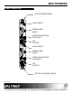
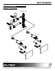
MULTITASKER PRODUCT DESCRIPTION 4 TOP RETAINER SCREW AUDIO INPUT 1 RGBHV/YPbPr INPUT 1 VIDEO EQUALIZATION FOR INPUT 1 4TP OUTPUT 1 AUDIO INPUT 2 RGBHV/YPbPr INPUT 2 VIDEO EQUALIZATION FOR INPUT 2 4TP OUTPUT 2 BOTTOM RETAINER SCREW 400-0433-003 4
MULTITASKER APPLICATION DIAGRAMS 5 DIAGRAM 1: TYPICAL SETUP MT115-110 TP115-111 TP115-111 400-0433-003 5
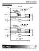
MULTITASKER DIAGRAM 2: INTERNAL VIEW MT115-110 INPUT OUTPUT POWER EQ H/W EQ SYNC HOR PROCESSING VER VIDEO 15-PIN HD S/W SIGNAL DETECT RED PAIR 1 BLUE PAIR 3 GREEN PAIR 2 4TP PLUG and PLAY AUDIO 3.5mm LEFT Stereo to Mono RIGHT POWER S/W SIGNAL DETECT EQ H/W EQ SYNC HOR PROCESSING VER VIDEO 15-PIN HD PAIR 4 RED PAIR 1 BLUE PAIR 3 GREEN PAIR 2 PLUG and PLAY AUDIO 3.
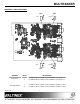
MULTITASKER DIAGRAM 3: SWITCH SETTINGS SW4 EQ1 SW6 GAIN1 EQ2 GAIN2 SW3 CONTROL Video Gain Video Equalization 400-0433-003 SW5 INPUT DESCRIPTION 1 Set SW6 to SW for software control and HW for a fixed gain = 1. 2 Set SW5 to SW for software control and HW for a fixed gain = 1. 1 Set SW4 to SW for software control and HW for hardware control. 2 Set SW3 to SW for software control and HW for hardware control.
MULTITASKER INSTALLING YOUR MT115-110 6 OPERATION Step 1. Determine the appropriate switch settings using Diagram 3 on page 7. 7.1 RS-232 CONTROL The MT115-110 has many advanced remote-control capabilities accessible through standard RS-232 communication. Control may be accomplished through a computer control system or any other device capable of sending RS-232 communication. Step 2. Turn off power to the MultiTasker system and disconnect from AC power. Step 3.
MULTITASKER 7.2 DESCRIPTION OF COMMANDS Each command consists of three Function, Card ID, and Unit ID. [ Function , Card ID , Unit ID ] COMMANDS parts: 1. [VER] This command displays the software version and card type for the MT115-110 card. Example: [VERC3U2] Command Format: [VERCn] VER= Function Cn = Card ID (n = slot # from 1 to max slots) C3 = Card ID or Group ID Example: U2 = Unit ID (optional for Unit ID 0) An MT115-110 card is in slot 3.
MULTITASKER 3. [CnS] Example: This command saves the card settings and displays the status. After the system is reset or powered off and on, the settings are restored. A MultiTasker with unit ID 1 has a front panel with part number MT101-101 and contains an MT103-122, MT103-123, and MT115-110. Send the command [?U1] and receive the following feedback: Cn = card number S = save configuration [(MT101-101U1)(MT103-122C01) (MT103-123C02)(MT115-110C03)] Example: Save the status by sending [C4S].
MULTITASKER 6. [STA1] 9. [TEST] This command enables automatic feedback from the front panel. The command affects any card with auto-feedback capability, not just the MT115-110. The default at power on or reset is STA0, off. For more details, see the [?Cn] command definition. This command performs a series of tests on the internal memory and displays a pass message if successful. Otherwise, failures are indicated. Command Format: [STA1] Upon completion, the system will display the results.
MULTITASKER 14. [HELP] Example: Set the equalization on Input 2 of C3 to a value of 32 by sending the command [EQ2=32C3]. The card will respond with feedback of “[ ]” once the command is executed. This command displays information available for the MultiTasker interface commands. Command Format: [HELPCn] Cn = Card ID (n = # from 1 to max slots) 12. [GAIN] Example: This command displays the gain setting for an input and selects that input for adjustment using the [+] and [-] commands.
MULTITASKER 17. [RSI] ID COMMANDS This command resets the card IDs in the system. After sending this command, each card ID in the system will match the slot number of the card. If the card is moved to another slot, its ID number will be the new slot number. The default card ID is the same as the card slot number. The next several commands allow the user to change the card ID to a value other than the slot number. Once the ID is changed, moving the card to another slot will not change the card ID.
MULTITASKER 20. [SID+] GROUP COMMANDS This command sets the card ID of all the cards in a system to their slot number plus the offset value. The next few commands are group commands. The use of groups allows several cards with the same functions to be controlled simultaneously using a single command. Up to 8 groups (G1-G8) may be defined in a MultiTasker system. These commands apply to all cards, not only the MT115-110.
MULTITASKER Example: Command Format: [RDGk] G5 consists of the C2, C4, and C6. Remove only C4 and C6 from the group by sending the command [RMC4C6G5]. The system will return the following feedback: Gk = Group ID (k = # from 1-8) Example: C2, C4, and C6 make up G5. Read the member data for G5 by sending the command [RDG5]. The system will return feedback as follows: [G5=C2] 24. [RMG] [G5=C2C4C6] This command may be used to delete an entire group, or all groups.
MULTITASKER Group Commands 22) [WR] 7.4.2 USING MENU MODE Group multiple cards 24) [RMG] Delete group TIP: It is best to disable the automatic feedback feature, [STA0]. The automatic feature will display after each setting change making the menus difficult to read. 25) [RD] 1. In order to enter Menu Mode, the system needs to be connected to a computer running RS-232 control software. 2. In the Terminal Window, press ENTER on the keyboard. 3.
MULTITASKER 7.4.
MULTITASKER 7.4.5 MENU MODE EXAMPLES TROUBLESHOOTING GUIDE All Menu Mode examples assume an MT115-110 is installed in slot 3. Start by clicking the mouse in the Terminal Window. Press ENTER and a list of available cards will be displayed. 8 We have carefully tested and found no problems in the supplied MT115-110 unit. However, we would like to offer the following suggestions: 8.1 LEDs ARE OFF Cause 1: 1. Set Video Equalization There is no power to the card.
MULTITASKER Cause 2: Signal is bad or missing. ALTINEX POLICIES Solution 1: Make sure the output is connected to the TP receiver. If there is still no display, see Solution 2. 9.1 LIMITED WARRANTY/RETURN POLICIES Please see the ALTINEX website at www.altinex.com for details on warranty and return policies. Solution 2: Bypass the MT115-110 and TP receiver and connect the output of the source directly to the monitor. If the display is good, then call ALTINEX at (714) 990-2300.