SPECIAL APPLICATION MANUAL PART NUMBER: 400-0199-006 DA1931CT TWISTED PAIR TO VIDEO + AUDIO RECEIVER USER’S GUIDE
SPECIAL APPLICATION TABLE OF CONTENTS Page PRECAUTIONS / SAFETY WARNINGS................ 2 GENERAL..........................................................2 INSTALLATION..................................................2 CLEANING.........................................................2 FCC NOTICE .....................................................2 ABOUT YOUR DA1931CT ....................................... 3 TECHNICAL SPECIFICATIONS.............................. 3 PRODUCT DESCRIPTION ..................
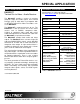
SPECIAL APPLICATION PRECAUTIONS / SAFETY WARNINGS 1.4 FCC NOTICE 1 Please read this manual carefully before using your DA1931CT. Keep this manual handy for future reference. These safety instructions are to ensure the long life of your DA1931CT and to prevent fire and shock hazards. Please read them carefully and heed all warnings. • 1.1 GENERAL • • Qualified ALTINEX service personnel or their authorized representatives must perform all service. 1.
SPECIAL APPLICATION ABOUT YOUR DA1931CT 2 TECHNICAL SPECIFICATIONS DA1931CT Twisted Pair to Video + Audio Receiver Specifications are subject to change. See www.altinex.com for up-to-date information. The DA1931CT provides a means of receiving computer video and audio signals over Twisted Pair-type (CAT-5) cable when used together with an ALTINEX Twisted Pair Video Transmitter, such as the DA1930CT. FEATURES/ DESCRIPTION The DA1931CT is compact and easy to use.
SPECIAL APPLICATION MECHANICAL DA1931CT Material 0.1” Al Finish ALTINEX Grey Top Panel Lexan Overlay Height 5.28 in (134 mm) Width 4.29 in (109 mm) Depth 0.98 in (25 mm) Weight 1.0 lb (0.45 kg) Ship Weight 1.6 lb (0.73 kg) T° Operating 10°C-40°C T° Maximum 50°C Humidity ELECTRICAL Input Twisted Pair Video/Sync/Audio Signals ALTINEX Standard Output Video Signals RGBHV/YPbPr - Video RGBHV - Sync 40,000 hrs Table 2.
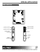
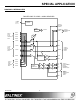
SPECIAL APPLICATION PRODUCT DESCRIPTION 4 LOOP 2 OUTPUT C-VIDEO OUTPUT LOOP 1 OUTPUT S-VIDEO OUTPUT RGBHV/YPbPr OUTPUT INPUT POWER VIDEO EQ.
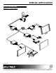
SPECIAL APPLICATION APPLICATION DIAGRAMS 5 DIAGRAM 1: TYPICAL SETUP 400-0199-006 6
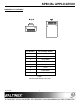
SPECIAL APPLICATION DIAGRAM 2: RJ-45 PINOUT Pin Number RJ-45 Output Signals 1 Orange/White 2 Orange 3 Green/White 4 Blue 5 Blue/White 6 Green 7 Brown/White 8 Brown Table 1 Standard 568B Wiring Color Code 400-0199-006 7
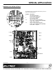
SPECIAL APPLICATION DIAGRAM 3: INTERNAL VIEW TWISTED PAIR TO VIDEO + AUDIO RECEIVER POWER 2.
SPECIAL APPLICATION DIAGRAM 4: DIP-SWITCH SETTINGS The DA1931CT has an internal Dip-Switch with 6 positions to achieve the following features: Position 1 Description Video Gain (G=1/G=2) Factory Default = OFF (G=2).
SPECIAL APPLICATION INSTALLING YOUR DA1931CT 6 OPERATION Step 1. Determine the settings required for Gain, Sync-On-Green, Horizontal and Vertical Sync Polarity. If necessary to change the factory defaults, open the unit and set the switches per DIAGRAM 4 on page 9. The DA1931CT requires only one adjustment to be made for optimal performance. Video Equalization is required for long cable lengths and may be adjusted to fine-tune the video display. 7.1 VIDEO EQUALIZATION Step 2.
SPECIAL APPLICATION 8.2 LED IS NOT GREEN Cause 1: There is no power. Solution: Disconnect the video input from the DA1931CT and verify the LED is on and red indicating power is present. Reconnect the computer output. If the LED is not green see Cause 2. Cause 2: There is no Sync signal. Solution: Verify the computer output is operating correctly by connecting it directly to a monitor. If the display is good, please call ALTINEX at (714) 990-2300. The source has a problem.