
User`s guide

SWITCHER
7
INSTALLING YOUR SWITCHER 6
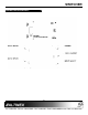
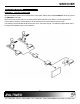
Step 1. Make sure that the correct power adapter
is used. The Altinex power adapter is
supplied with the unit.
Step 2. Connect the power adapter to the power
port.
CAUTION: The POWER port and the
INPUT SELECT port use the same
connector type. Make sure the power
adapter is connected to the POWER port.
Step 3. The POWER indicator light and the
INPUT 2 indicator light should turn ON.
Step 4. Connect the SW1956CT inputs to the
outputs of the DA1930CT VGA+AUDIO to
CAT-5/6 Transmitters.
Step 5. Connect a cable from the output port of
the SW1956CT to the input port of the
DA1931CT CAT-5/6 to VGA+AUDIO
Receiver.
Step 6. If the remote control switch is to be used,
connect the RC5203CC to the INPUT
SELECT port.
CAUTION: The POWER port and the
INPUT SELECT port use the same
connector type. Make sure the control
switch is connected to the INPUT
SELECT port.
Step 7. Verify that the picture quality on the
display is good. If a signal is not being
received, make sure that the display is
compatible with the resolution of the
computer graphics card.
OPERATION 7
There are no settings to adjust on the SW1956CT
Auto-Switcher. The SW1956CT will operate
successfully as long as cables are attached
properly and other technical specifications are
followed.
AUTO-SWITCH MODE
The SW1956CT automatically selects the INPUT 2
port if there are no active signals present. If there is
an active signal on INPUT 2 and not on INPUT 1,
then the SW1956CT will maintain INPUT 2 as the
active port. However, when an active signal is
applied to INPUT 1, the SW1956CT will switch to
INPUT 1.
If there are active signals on INPUT 1 and
INPUT 2, the SW1956CT will automatically switch
to INPUT 1.
MANUAL SWITCH MODE
Manual override is accomplished via a contact
closure on the INPUT SELECT jack. Manual Switch
Mode disables Auto-Switching.
Included with the SW1956CT is an external manual
switch with a six foot cable, Altinex part number
RC5203CC. This switch may be used for manual
control, or the contact closure may be made from a
control system. This port uses a 2.5mm
mini-coaxial remote control jack and it is located
next to the CAT-5 OUTPUT.
INPUT 1 will be selected when the remote control
switch is connected to the INPUT SELECT jack and
the contact is closed. INPUT 2 will be selected if
the contact is open.
CAUTION: The connector used for the INPUT
SELECT port is the same type as is used for the
POWER connector. Use caution to ensure the
switch is connected to the correct port.