SWITCHER MANUAL PART NUMBER: 400-0378-001 SW1956CT 2–IN, 1–OUT CAT-5 AUTO-SWITCHER USER’S GUIDE
SWITCHER TABLE OF CONTENTS Page PRECAUTIONS / SAFETY WARNINGS ..............2 GENERAL..........................................................2 INSTALLATION..................................................2 CLEANING.........................................................2 FCC / CE NOTICE..............................................2 ABOUT YOUR SWITCHER ..................................3 TECHNICAL SPECIFICATIONS...........................3 DESCRIPTION OF SW1956CT............................
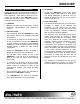
SWITCHER PRECAUTIONS / SAFETY WARNINGS 1.4 CLEANING 1 • Please read this manual carefully before using your SW1956CT Switcher. Keep this manual handy for future reference. These safety instructions are to ensure the long life of your SW1956CT and to prevent fire and shock hazard. Please read them carefully and heed all warnings. 1.5 FCC / CE NOTICE 1.1 GENERAL • Qualified ALTINEX service personnel, or their authorized representatives must perform all service.
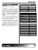
SWITCHER ABOUT YOUR SWITCHER 2 TECHNICAL SPECIFICATIONS SW1956CT 2-In, 1 Out CAT-5 Auto-Switcher FEATURES/DESCRIPTI ON Inputs Input Connector Outputs Output Connector Compatibility The SW1956CT is a 2-In, 1-Out CAT-5 Auto-Switcher. The SW1956CT automatically switches on signal detection, but may also be controlled manually if desired. The SW1956CT is designed to switch Altinex CAT-5/6 Twisted Pair Transmitter and Receiver signals.
SWITCHER DESCRIPTION OF SW1956CT 4 4
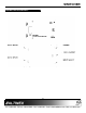
SWITCHER APPLICATION DIAGRAM 5 DIAGRAM 1 : TYPICAL CONNECTION Altinex provides a remote control switch with a 6 foot cable, Altinex part number RC5203CC, which will control the SW1956CT manually. When the remote control switch is connected to the INPUT SELECT jack, INPUT 1 will be selected if the channel select contact is closed. INPUT 2 will be selected if the channel select contact is open. The switching will be identical whether there are one or two active signals.
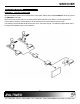
SWITCHER DIAGRAM 2 : INTERNAL VIEW CONTACT CLOUSURE SIGNAL DETECT INPUT1 RJ45 CAT-5 OUTPUT CAT-5 INPUT1 RJ45 INPUT2 INPUT2 2.
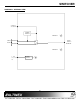
SWITCHER INSTALLING YOUR SWITCHER 6 OPERATION Step 1. Make sure that the correct power adapter is used. The Altinex power adapter is supplied with the unit. 7 There are no settings to adjust on the SW1956CT Auto-Switcher. The SW1956CT will operate successfully as long as cables are attached properly and other technical specifications are followed. Step 2. Connect the power adapter to the power port. AUTO-SWITCH MODE CAUTION: The POWER port and the INPUT SELECT port use the same connector type.
SWITCHER TROUBLESHOOTING GUIDE 8 Solution 2: Connect a properly formatted signal from an Altinex CAT-5/6 Transmitter to INPUT 1. If the switcher does not switch to INPUT 1, see Solution 3. We have carefully tested and have found no problems in the supplied SW1956CT unit. However, we would like to offer the following suggestions: Solution 3: Bypass the switcher and connect the output of the transmitter directly to the input of the receiver. If the display is good, then call ALTINEX at (714) 990-2300. 8.
SWITCHER Cause 4: Cable connections are incorrect. ALTINEX POLICY Solution: Make sure that cables are properly connected. Also, make sure that the continuity and wiring are good. If there is still no display present, see Cause 5. 9.1 LIMITED WARRANTY/RETURN POLICY Cause 5: The display has a problem. 9.2 CONTACT INFORMATION Solution: Make sure the display has power and is turned ON. If there is still no display, please call Altinex at (714) 990-2300. 9 Please see the Altinex website at www.