SPECIAL APPLICATION MANUAL PART NUMBER: 400-0199-003 DA1931CT CAT-5 TO VGA + AUDIO RECEIVER USER’S GUIDE
SPECIAL APPLICATION TABLE OF CONTENTS Page PRECAUTIONS / SAFETY WARNINGS ..............2 GENERAL..........................................................2 INSTALLATION .................................................2 CLEANING.........................................................2 FCC / CE NOTICE..............................................2 ABOUT YOUR DA1931CT ...................................3 TECHNICAL SPECIFICATIONS...........................3 PRODUCT DESCRIPTION ................................
SPECIAL APPLICATION PRECAUTIONS / SAFETY WARNINGS • 1 Please read this manual carefully before using your DA1931CT. Keep this manual handy for future reference. These safety instructions are to ensure the long life of your DA1931CT and to prevent fire and shock hazard. Please read them carefully and heed all warnings. 1.1 GENERAL • Qualified ALTINEX service personnel, or their authorized representatives must perform all service. 1.
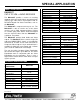
SPECIAL APPLICATION ABOUT YOUR DA1931CT 2 MECHANICAL Material Finish Top Panel Height (inches) Width (inches) Depth (inches) Weight (pounds) Ship Weight (pounds) T° Operating T° Maximum Humidity MTBF (calculations) DA1931CT CAT-5 TO VGA + AUDIO RECEIVER The DA1931CT provides a means of receiving computer video and audio signals over twisted pair (CAT-5) type cable when used together with an ALTINEX Twisted Pair Video Transmitter, such as the DA1930CT. The DA1931CT is compact and easy to use.
SPECIAL APPLICATION PRODUCT DESCRIPTION 400-0199-003 4 4
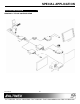
SPECIAL APPLICATION APPLICATION DIAGRAM 5 DIAGRAM 1: TYPICAL CONFIGURATION 400-0199-003 5
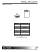
SPECIAL APPLICATION DIAGRAM 2: RJ-45 PINOUT TOP 1 1 8 FRONT Pin Number RJ-45 Output Signals 1 Orange/White 2 Orange 3 Green/White 4 Blue 5 Blue/White 6 Green 7 Brown/White 8 Brown Table 1 Standard 568B Wiring Color Code 400-0199-003 6 8
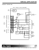
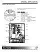
SPECIAL APPLICATION DIAGRAM 3: INTERNAL VIEW VGA + AUDIO TO CAT-5 RECEIVER POWER 2.
SPECIAL APPLICATION DIAGRAM 4: DIP SWITCH SETTINGS The DA1931 has an internal Dip-Switch with 6 positions to achieve following features: Position Description 1 Video Gain (G=1/G=2) SW1 x1 R45 C35 Factory Default = G1.
SPECIAL APPLICATION INSTALLING YOUR DA1931CT 6 OPERATION Step 1. Determine the settings required for Gain, Sync On Green, Horizontal Sync Polarity and Vertical Sync Polarity. If necessary to change the factory defaults, open the unit and set the switches per DIAGRAM 4 on page 8. The DA1931CT requires only one adjustment to be made for optimal performance. Video Equalization is required for long cable lengths and may be adjusted to fine tune the video display. 7.
SPECIAL APPLICATION TROUBLESHOOTING GUIDE 8.3 NO SOUND 8 We have carefully tested and have found no problems in the supplied DA1931CT. However, we would like to offer suggestions for the following: Cause 1: The source has a problem. Solution: Check the source and make sure that there is a signal present and all source connections are correct. If the source is working and there is still no sound, see Cause 2. Cause 2: The volume is too low. Solution: Increase the AUDIO GAIN toward maximum.
SPECIAL APPLICATION 8.5 RECEIVING DISPLAY QUALITY IS POOR Cause 1: The source has a problem. Solution: Check the image on the local monitor and verify the quality is good. If the local image is good, see Cause 2. Cause 2: Video equalization required. Solution: Adjust the VIDEO EQUALIZATION on the DA1931CT. Long cable runs may require adjustment on both the DA1930CT and the DA1931CT. If the image is still not correct, call ALTINEX at (714) 990-2300. ALTINEX POLICY 9.