
User`s guide


DISTRIBUTION AMPLIFIERS
400-0087-004 5
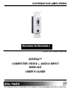
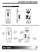
4.1 VIDEO INPUT
The computer input is a 15-pin HD connector on
the front of the ICS2000-W/ISC2000-I. It is
connected to the video output of a desktop
computer or similar device.
PIN No. Input signals on 15-pin HD
female connector
1 RED
2 GREEN
3 BLUE
4 SIGNAL RETURN
5 SIGNAL RETURN
6 SIGNAL RETURN
7 SIGNAL RETURN
8 SIGNAL RETURN
9 VESA POWER INPUT
10 SIGNAL RETURN
11 SIGNAL RETURN
12 SDA
13 HORIZONTAL
14 VERTICAL
15 SCL
Table 4. ISC2000-W/ISC2000-I’s Video Input Pins
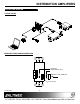
4.2 VIDEO OUTPUT
The ISC2000-W/ISC2000-I offers a video output
through a 10-pin IDC connector on the back of the
ISC2000-W/ISC2000-I. The Distribution Amplifier
allows a connection to different types of projectors
or monitors using Altinex breakout cables.
PIN No. VIDEO OUTPUTS ON 10-PIN IDC
BLOCK
1
RED
2
GROUND
3
GREEN
4
GROUND
5
BLUE
6
GROUND
7
HORIZONTAL
8
GROUND
9
VERTICAL
10
SIGNAL RETURN
Table 5. 10-Pin IDC Connector Video Output Pins
4.3 AUDIO INPUT & OUTPUT
The ISC2000-W/ISC2000-I accepts computer audio
input and offers balanced stereo output through a
terminal block connector on the back. There is a
3.5mm jack for computer audio input. A 5-pin
terminal block is available for stereo audio
transmission to the main sound system. These
connectors are easily adaptable to stereo mini or
RCA type connectors.
PIN No. AUDIO OUTPUTS ON 5-PIN MALE
TERMINAL BLOCK
1 L+IN (Left Channel)
2 L-IN (Left Channel)
3 SIGNAL RETURN
4 R+IN (RIGHT Channel)
5 R-IN (RIGHT Channel)
Table 6. 5-Pin Male Terminal Block for Audio
Output
4.4 POWER INPUT CONNECTOR
The ISC2000-W/ISC2000-I has a power terminal
block for connection to a 9VDC 500mA external
adapter. Power regulation is provided inside the
unit.
PIN No. INPUT POWER ON 2-PIN MALE
TERMINAL BLOCK
1 +9VDC
2 GND
Table 7. 2-Pin Male Terminal Block for Power Input