
User`s guide
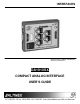

INTERFACES
8
8
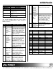
Model No. Description
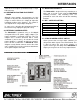
RACK MOUNT ACCESSORIES
DA1291SX
Power adapter security kit.
DA1295SX
Rack/Wall mount brackets for
DA1900 series.
COMBO-PACK
VGA+MAC INPUT & OUTPUT
cables
SUPER-PACK
VGA+MAC+SUN/SGI INPUT &
OUTPUT cables
Table 9. Optional accessories
The standard available cables are 3 feet in length,
please call 1-714-990-2300 for a wider selection of
cables (6 ft, 12 ft).
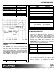
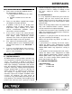
FAQ (FREQUENTLY ASKED QUESTIONS) 9
No: Question Answer
1 Why does
the
termination
switch
have to be
ON?
The Termination switch
should be ON if local monitor
is not connected through a
straight cable. It will be OFF
only if a monitor breakout
cable is used at local monitor
output connector.
2 When and
why do I
need to
use the
Horizontal
Position
Dip-
switch?
The Horizontal Position Dip-
switch enables or disables
the control of the horizontal
position of the image using
the control knob on the
DA1910SX. First, adjust the
horizontal position using the
monitor or projector’s control,
and then use the Horizontal
position control of the
DA1910SX, if needed.
3 What dip-
switch do I
set to get
the
composite
SYNC
output?
If the desired output signal is
composite sync, then turn
OFF the H & V OUTPUT Dip-
switch and connect only 4
wires (RGBS) to RED,
GREEN, BLUE, and H/C
SYNC Connectors.
4 When and
why would
I use the
Sync on
Green dip-
The DA1910SX does not
separate Sync signal from
Green, but if the desired
output is in RGsB format
regardless of input signal,
switch,
although
the unit
does not
separate
Sync from
Green?
turn the Sync on Green dip-
switch to the ON position.
5 When do I
use the “H
& V out”
Dip-
switch?
If the desired output is in
RGBHV format, turn ON the
H & V Out Dip-switch. If the H
& V Out dip switch is OFF,
then the output signal may
have Composite Sync
present on the Horizontal
Sync Connector.
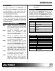
6 What is a
Computer
Video Card
Pin-outs?
See the following table for
Common Computer Video
Card Pin-outs
Table 10. Frequently Asked Questions
PINS MAC VGA SUN
A1
n/a n/a Red
A2
n/a n/a Green
A3
n/a n/a Blue
1
Red Gnd Red N/C
2
Red Green N/C
3
C.Sync Blue Sense
4
ID Bit 01 ID Bit Sense Rtn
5
Green N/C C. Sync Sens
6
Green Gnd. Red Rtn. N/C
7
ID Bit 02 Green Rtn. N/C
8
N/C Blue Rtn. N/C
9
Blue N/C N/C
10
ID Bit 03 Gnd N/C
11
C/V Gnd. ID Bit
12
V. Sync ID Bit
13
Blue Gnd. H. Sync.
14
H. Gnd V. Sync
15
H. Sync N/C
Table 11. Common Computer Video Card pin-outs