MAXCS Release 7.
Contents Introduction.................................................................................................................................................... 3 Requirements ................................................................................................................................................. 3 MultiVoIP Gateway Configuration ..................................................................................................................
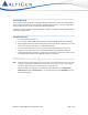
Introduction This document provides guidelines for setting up a MultiTech gateway as a remote SIP trunking gateway, and for configuring SIP extensions. This document uses MVP410 as an example. The same configuration should also apply to other models of the MultiTech MultiVoIP gateway. The firmware version for MVP410 used in this example is 6.09.0a. The AltiGen IP phone firmware version needs to be 2xxx (SIP-based). Requirements • You must have MaxCS release 7.0.
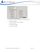
2. Select Configuration > Call Signaling > SIP. Set Signaling Port to 5060. 3. Select Configuration > Call Signaling > NAT Traversal. In our example, we do not use the STUN protocol, so the checkbox is cleared. 4. Select Advanced > Packetization Time. • 5. Set G.729@8Kbps to 10 (ms) Click Copy Channel to copy the setting to all the channels. MAXCS 7.
6. Select Phone Book > Outbound Phone Book. 7. Either create a new entry or edit an existing entry with the following parameters: • Check Accept Any Number. • Set IP Address to the MaxCS IP Address, 10.10.0.237. • Set Protocol Type as SIP. • Set Transport Protocol as UDP. • Set SIP Port Number as 5060. MAXCS 7.
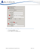
Enterprise Manager Configuration 1. Open Enterprise Manager and log in. 2. Select the Codec tab and the IP Codec sub-tab. MAXCS 7.
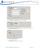
3. Add a new codec profile named MVP Gateway. Set the following parameters: • Set Codec to Prefer G.723.1 support G.729 (the codec between MaxCS and the MultiVoIP Gateway, in this example, is G.723) • Set both DTMF Delivery and SIP Early Media to Default 4. Select Enterprise Manager > IP Dialing Table. 5. Add an entry (Server ID is 1 in this example) with the following parameters: • Set Server Name to MVP Gateway • Set Sever IP Address to 10.10.101.81 • Set Dialing Scheme to Enblock.
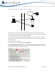
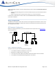
The “Connect Voice Stream to Server” Option PSTN IP Address 10.10.0.237 SIP Singa MaxCS Tel 5102520004 Intranet (VPN/Frame Relay) naling SIP S ingan ali MVP 410 Voice Stream ng AltiGen IP phone Ext 210 In the figure above, a call comes from PSTN to the gateway and connects to AltiGen IP phone 210. There are two SIP signaling paths. The first signaling path is between the MultiVoIP gateway and MaxCS. The second path is between the AltiGen IP phone and MaxCS.
Under the following conditions, the system administrator will need to check the Connect Voice Stream to Server option: • When the Voice Recording feature is used on the AltiGen IP phone (or the FXS extension behind MVP410) • When a supervisor wants to silently monitor, barge in to, or coach the extension In these cases, the administrator needs to make sure the bandwidth between headquarters and the branch office is sufficient. Basic Configuration The MVP410 has 4 FXS/FXO channels.
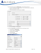
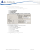
Follow these steps to configure the SIP extensions: 1. In MaxCS Administrator, select Extension Configuration. 2. Add two virtual extensions, 251 and 252, with the following parameters: • For Type, select IP Extension • Check Enable IP Extension • Select Static IP Address • Set Static IP Address to 10.10.101.81 (the IP address of the MultiVoIP gateway) 3. Open the MultiVoIP configuration tool. 4. Select Configuration > Voice/Fax and configure these parameters: 5.
6. Select Configuration > Interface and configure these parameters: • Set Select Channel to Channel 1 • Set Interface Type to FXS (Loop Start) • Set Caller ID Type to BellCore • Check the Caller ID Enable check box MAXCS 7.
7. 8. Select Phone Book > Outbound Phone Book and create an entry with the following parameters: • Check Accept Any Number • Set IP address to 10.10.0.237(the MaxCS IP address) • Set Protocol Type to SIP • Set SIP Transport Protocol to UDP • Set SIP Port Number to 5060 Select Phone Book > Inbound Phone Book and create a new entry with these parameters: • For Remove Prefix enter 251 • Set Channel Number to Channel 1 (this will bind Channel 1 to extension 251) MAXCS 7.
9. Repeat the same process for extension 252 by adding a new entry where Remove Prefix is 252 and Channel Number is Channel 2. 10. Under Save & Reboot, click OK. Wait for the MVP410 to reboot itself. 11. Attach analog phone sets to the MVP410 system (FXO/FXS port). 12. Make some test calls among ext 104, ext 251 and ext 252. SIP-Tie Trunk Configuration for Incoming Calls from PSTN Before you configure SIP-Tie trunks, check that all of the requirements in the Requirements section on page 3 have been met.
To configure SIP-Tie Trunks, follow these steps: 1. Open the MultiVoIP configuration tool. 2. Select Configuration > Voice/Fax and configure these parameters: 3. • Set Select Channel to Channel 3 • Set DTMF to Out of Band – Fixed Duration • Set Out Of Band Mode to SIP Info • Set Coder to Manual • Set Selected Coder to G.723.1@6.3kbps • Set Auto Call/OffHook Alert to Auto Call • Check Generate Local Dial Tone.
• Set Caller ID Type to BellCore • Check the Caller ID Enable check box 4. Select Configuration > Interface. 5. Click the Supervision button and set the following parameters: • Check the Answer Delay checkbox • Set Answer Delay Timer to 1 6. These settings only apply to Channel 3. Apply these setting to other FXO channels, if there are others. 7. Select Save Setup > Save & Reboot, click OK. Wait for the gateway to reboot itself. Verification 1.
Analog extensions behind the MVP gateway are optional. If the analog extensions are required, complete the steps in the section SIP Extension Configuration before you proceed. To configure the SIP-Tie Trunks, follow these steps: 1. Open MaxCS Administrator and select System > System Configuration > First Digit Assignment. 2. Assign digit 8 to IP Trunk Access. 1. Select PBX >Trunk Configuration >General. 2. Highlight one of the SIP-Tie trunks. 3. Set Trunk Access Code to 8. 4.
5. Log into the MultiVoIP tool. 6. Select Phone Book > Inbound Phone Book and add a new entry with the following parameters: • Set Remove Prefix to 222 Important! You can pick any prefix, but once the prefix is selected, it cannot be used as an extension number. • Set Channel Number to Channel 3 7. Repeat the same settings for FXO port Channel 4. (Apply the settings only for channels configured as FXO ports instead of FXS ports.) 8. Under Save Setup > Save & Reboot, click OK.
Outgoing Calls to PSTN Using Out Call Routing (Optional) To make a call to the outside though the MVP gateway requires dialing a number with a “strange” prefix, which may not be intuitive for most users. For example, users may expect to dial “914081231234” instead of “8-1-222-14081231234.” Proper configuration of out-call routing in MaxCS can resolve this problem.
To configure outgoing PSTN call via Out-call routing, follow these steps: 1. Log into MaxCS Administrator and select PBX > Trunk Configuration. 2. Set all analog trunk Access Codes to None (the H.323-Tie or SIP-Tie trunk access code should still be “8”). 3. Select System > System Configuration > First Digit Assignment. 4. Assign digit 9 to Route Access. 5. Select PBX > Out Call Routing Configuration > Route Definition. 6. Add a new entry named Local Trunk. MAXCS 7.
7. Select all the analog trunks (in this example, from “02:000” to “02:011”) as Member Trunks. 8. Click Apply. 9. Select PBX > Out Call Routing Configuration > Default Routes and configure these parameters: • Set Local Route entry 1 to 1: Local Trunk • Set Long Distance Route entry 1 to 1: Local Trunk • Set International Route entry 1to 1: Local Trunk • Set Emergency Call Route entry 1to 1: Local Trunk 10. Click Apply. MAXCS 7.
Verification At this point, you should be able pick up extension 104 and make an outbound call by dialing 914081231234. Outpost Digits In Figure 3, when a user makes a call to 15102520004 from extension 104, it would be nice if the system would send the call through the MVP gateway’s FXO port channel 3 or channel 4. To achieve this, MaxCS needs to outpost the digits “2222520004” to the gateway. To do this, MaxCS must remove the first 4 digits of “15102520004”, and then insert “1222” to the head.
5. 6. Select PBX > Out Call Routing Configuration > Dialing Pattern and add a new entry: • Set Prefix to 1510 • Set Pattern length including prefix to 11 • Set Route Priority 1 to 2: Area510 MVP Click Apply. MAXCS 7.
Verification 1. Follow Figure 3. Use extension 104 to dial 15102520004. The call should go through the MVP gateway. 2. Use extension 104 to dial 14081231234. The call should go through local trunks instead of the gateway.
3. 4. Move extensions 210, 251 and 252 to the Members list. (Extensions 251 and 252 are optional if you only have AltiGen IP phone 210.) • For Dialed Number enter 91510 • For Translate To enter 81222 Click Apply. Verification From extension 210 and extension 251 in the remote site, make a call to 9-1-510-250004. MaxCS should send the call through the MultiVoIP gateway’s FXO ports. Note: With this approach, the user will always need to dial 12 digits, even when placing a local call.
Under Dialed Digit Translator: 1. Log into MaxCS Administrator and select System > System Configuration > Number Plan. 2. From the Select Digit Translator list, select Extension Dialed Digit Translator. 3. Create a new Extension Group named 911 for Area510. 4. Move extensions 210, 251, and 252 to the Members list. (Extensions 251 and 252 are optional if you only have AltiGen IP phone 210.) 5.
To configure emergency gateway dialing, follow these steps: 1. Log into the MultiVoIP configuration tool and select Phone Book > Inbound Phone Book. 2. Add a new entry. • Set Remove Prefix to 911 • Set Add Prefix to 911 Note: • If you want to do some tests without really sending the call to the 911 center, you can temporarily change this value to, for example, your cell phone number. Set Channel Number to Channel 3 3. Repeat the same settings for FXO port Channel 4.
AltiGen Technical Support AltiGen does not provide general configuration support for EdgeWater or AudioCodes products. For general configuration information, refer to your AudioCodes or EdgeMarc documentation. AltiGen provides technical support to Authorized AltiGen Partners and distributors only. End user customers, please contact your Authorized AltiGen Partner for technical support.