
IP Phone User Manual


Table Of Contents
6 IP 720 User Manual
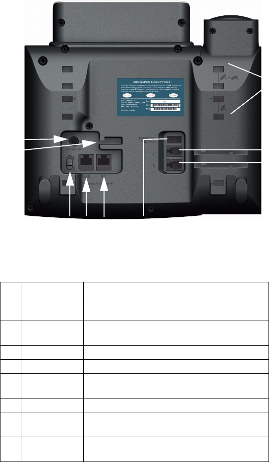
Figure 2. IP 720 Phone, Bottom View
1 DC Port Connects to power outlet
2 Power Cable
Restraint
Secures the power cable, preventing it from
accidentally being pulled out
3 DC/PoE Switch Switches between DC power and Power over
Ethernet
4 LAN Port Connects to network (10/100/1000 Base T)
5 PC Access Port Connects to PC (10/100/1000 Base T)
6 Plantronics
PSB Port
(Plantronics serial bus port) Connects to a
Plantronics wireless headset base
7 Handset Port Connects to a handset
8 Headset Port Connects to a non-amplified headset with RJ9
connector
9 Slots for the
Phone Stand
Four slots on each side for inserting the phone
stand to set the phone at the desired angle
5
4
3
1
9
2
6
8
7