
User guide


5–32 Chapter 5: Functional Description—ALTMEMPHY
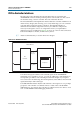
PHY-to-Controller Interfaces
External Memory Interface Handbook Volume 3 December 2010 Altera Corporation
Section II. DDR3 SDRAM Controller with ALTMEMPHY IP User Guide
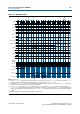
For half-rate designs, the AFI allows the controller to issue reads and writes that are
aligned to either half-cycle of the half-rate
phy_clk
, which means that the datapaths
can support multiple data alignments—word-unaligned and word-aligned writes and
reads. Figure 5–15 and Figure 5–16 display the half-rate write operation.
After calibration process is complete, the sequencer sends the write latency in number
of clock cycles to the controller.
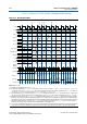
Figure 5–17 and Figure 5–18 show word-aligned writes and reads. In the following
read and write examples the data is written to and read from the same address. In
each example,
ctl_rdata
and
ctl_wdata
are aligned with controller clock (
ctl_clk
)
cycles. All the data in the bit vector is valid at once. For comparison, refer Figure 5–19
and Figure 5–20 that show the word-unaligned writes and reads.
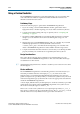
1 The
ctl_doing_rd
is represented as a half-rate signal when passed into the PHY.
Therefore, the lower half of this bit vector represents one memory clock cycle and the
upper half the next memory clock cycle. Figure 5–20 on page 5–37 shows separated
word-unaligned reads as an example of two
ctl_doing_rd
bits are different.
Therefore, for each x16 device, at least two
ctl_doing_rd
bits need to be driven, and
two
ctl_rdata_valid
bits need to be interpreted.
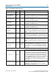
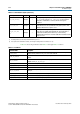
The AFI has the following conventions:
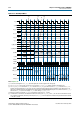
Figure 5–15. Half-Rate Write with Word-Unaligned Data
Figure 5–16. Half-Rate Write with Word-Aligned Data
00 11 0001
00
11
0110 00
-- a x cb xd
ctl_clk
ctl_dqs_burst
ctl_wdata_valid
ctl_wdata
00
10
11
00
00
11
00
-- ba --dc
ctl_clk
ctl_dqs_burst
ctl_wdata_valid
ctl_wdata