
User guide


5–26 Chapter 5: Functional Description—ALTMEMPHY
ALTMEMPHY Signals
External Memory Interface Handbook Volume 3 December 2010 Altera Corporation
Section II. DDR3 SDRAM Controller with ALTMEMPHY IP User Guide
aux_scan_clk
Output 1
Low frequency scan clock supplied primarily to
clock any user logic that interfaces to the PLL and
DLL reconfiguration interfaces.
aux_scan_clk_reset_n
Output 1
This reset output asynchronously asserts (drives
low) when
global_reset_n
is asserted and
de-assert (drives high) synchronous to
aux_scan_clk
when
global_reset_n
is
de-asserted. It allows you to reset any external
circuitry clocked by
aux_scan_clk
.
Write Data Interface
ctl_dqs_burst
Input
MEM_IF_DQS_WIDTH
×
DWIDTH_RATIO
/ 2
When asserted,
mem_dqs
is driven. The
ctl_dqs_burst
signal must be asserted before the
ctl_wdata_valid
signal and must be driven for
the correct duration to generate a correctly timed
mem_dqs
signal.
ctl_wdata_valid
Input
MEM_IF_DQS_WIDTH
×
DWIDTH_RATIO
/ 2
Write data valid. Generates
ctl_wdata
and
ctl_dm
output enables.
ctl_wdata
Input
MEM_IF_DWIDTH
×
DWIDTH_RATIO
Write data input from the controller to the PHY to
generate
mem_dq
.
ctl_dm
Input
MEM_IF_DM_WIDTH
×
DWIDTH_RATIO
DM input from the controller to the PHY.
ctl_wlat
Output 5
Required write latency between address/command
and write data that is issued to ALTMEMPHY
controller local interface.
This signal is only valid when the ALTMEMPHY
sequencer successfully completes calibration, and
does not change at any point during normal
operation.
The legal range of values for this signal is 0 to 31;
and the typical values are between 0 and ten, 0
mostly for low CAS latency DDR memory types.
Read Data Interface
ctl_doing_rd
Input
MEM_IF_DQS_WIDTH
×
DWIDTH_RATIO
/ 2
Doing read input. Indicates that the DDR3 SDRAM
controller is currently performing a read operation.
The controller generates
ctl_doing_rd
to the
ALTMEMPHY megafunction. The
ctl_doing_rd
signal is asserted for one
phy_clk
cycle for every
read command it issues. If there are two read
commands,
ctl_doing_rd
is asserted for two
phy_clk
cycles. The
ctl_doing_rd
signal also
enables the capture registers and generates the
ctl_mem_rdata_valid
signal. The
ctl_doing_rd
signal should be issued at the same
time the read command is sent to the ALTMEMPHY
megafunction.
ctl_rdata
Output
DWIDTH_RATIO
×
MEM_IF_DWIDTH
Read data from the PHY to the controller.
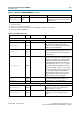
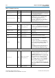
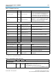
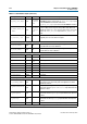
Table 5–4. AFI Signals (Part 2 of 3)
Signal Name Type Width (1) Description