
User guide


Chapter 5: Functional Description—ALTMEMPHY 5–9
Block Description
December 2010 Altera Corporation External Memory Interface Handbook Volume 3
Section II. DDR3 SDRAM Controller with ALTMEMPHY IP User Guide
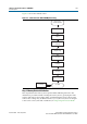
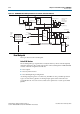
Figure 5–5 shows the calibration flow.
Step 1: Memory Device Initialization
This step initializes the memory device per the DDR3 SDRAM specification. The
initialization procedure includes resetting the memory device, specifying the mode
registers and memory device ODT setting, and initializing the memory device DLL.
Some of these settings may be different to those you set; however, these are changed
to the correct values (at the end of calibration) in “Step 8: Prepare for User Mode”.
Figure 5–5. Calibration Flow—DDR3 SDRAM (with leveling)
Memory Device
and PHY Initialization
Write Clock
Path Setup
Write Leveling
Write Training
Patterns
Postamble
Read and Write
Datapath Timing
Address and Command
Clock Cycle
Read Resynchronization
Clock Phase
User Mode
Prepare for User Mode
VT Tracking