
User guide


5–4 Chapter 5: Functional Description—ALTMEMPHY
Block Description
External Memory Interface Handbook Volume 3 December 2010 Altera Corporation
Section II. DDR3 SDRAM Controller with ALTMEMPHY IP User Guide
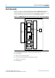
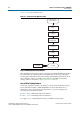
Figure 5–2 shows the calibration flow.
Step 1: Memory Device Initialization
This step initializes the memory device according to the DDR3 SDRAM specification.
The initialization procedure includes resetting the memory device, specifying the
mode registers and memory device ODT setting, and initializing the memory device
DLL. Calibration requires overriding some of the user-specified mode register
settings, which are reverted in “Step 7: Prepare for User Mode”.
Step 2: Write Training Patterns
In this step, a pattern is written to the memory to be read in later calibration stages.
The matched trace lengths to DDR3 SDRAM devices mean that after memory
initialization, write capture functions. The pattern is
0x30F5
and comprises the
following separately written patterns:
■ All
0
:
‘b0000
- DDIO high and low bits held at
0
■ All
1:
‘b1111
- DDIO high and low bits held at
1
■ Toggle:
‘b0101
- DDIO high bits held at
0
and DDIO low bits held at
1
Figure 5–2. Calibration Flow—Without Leveling
Memory Device
and PHY Initialization
User Mode
Write Training
Patterns
Read Resynchronization
Clock Phase
Prepare for User Mode
Address and Command
Clock Cycle
Postamble
Read and Write
Datapath Timing
VT Tracking