
User guide


7–16 Chapter 7: Functional Description—High-Performance Controller II
Top-level Signals Description
External Memory Interface Handbook Volume 3 December 2010 Altera Corporation
Section II. DDR3 SDRAM Controller with ALTMEMPHY IP User Guide
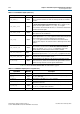
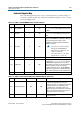
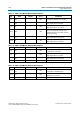
Table 7–6 shows the DDR3 SDRAM HPC II CSR interface signals.
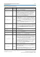
local_rdata[]
Output
Read data bus. The width of
local_rdata
is twice that of the memory data
bus for a full rate controller; four times the memory data bus for a half rate
controller.
local_rdata_error
Output
Asserted if the current read data has an error. This signal is only available if
the Enable Error Detection and Correction Logic option is turned on. This
signal is asserted together with the
local_rdata_valid
signal.
If the controller encounters double-bit errors, no correction is made and the
controller asserts this signal.
local_rdata_valid
Output
Read data valid signal. The
local_rdata_valid
signal indicates that valid
data is present on the read data bus.
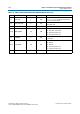
local_ready
Output
The
local_ready
signal indicates that the controller is ready to accept
request signals. If the
local_ready
signal is asserted in the clock cycle that
a read or write request is asserted, that request is accepted. The
local_ready
signal is deasserted to indicate that the controller cannot
accept any more requests. The controller is able to buffer eight read or write
requests.
local_refresh_ack
Output
Refresh request acknowledge, which is asserted for one clock cycle every
time a refresh is issued. Even if the Enable User Auto-Refresh Controls
option is not selected,
local_refresh_ack
still indicates to the local
interface that the controller has just issued a refresh command.
local_self_rfsh_ack
Output
Self refresh request acknowledge signal. This signal is asserted and
deasserted in response to the
local_self_rfsh_req
signal from the user.
local_power_down_ack
Output
Auto power-down acknowledge signal. This signal is asserted for one clock
cycle every time auto power-down is issued.
ecc_interrupt
Output
Interrupt signal from the ECC logic. This signal is asserted when the ECC
feature is turned on, and an error is detected. This signal remains asserted
until the user logic clears the error through the CSR interface.
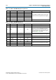
Table 7–5. Local Interface Signals (Part 3 of 3)
Signal Name Direction Description
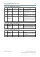
Table 7–6. CSR Interface Signals (Part 1 of 2) (Part 1 of 2)
Signal Name Direction Description
csr_addr[]
Input Register map address.The width of
csr_addr
is 16 bits.
csr_be[]
Input
Byte-enable signal, which you use to mask off individual bytes during writes.
csr_be
is active high.
csr_wdata[]
Input Write data bus. The width of
csr_wdata
is 32 bits.
csr_write_req
Input
Write request signal. You cannot assert
csr_write_req
and
csr_read_req
signals at the same time.
csr_read_req
Input
Read request signal. You cannot assert
csr_read_req
and
csr_write_req
signals at the same time.
csr_rdata[]
Output Read data bus. The width of
csr_rdata
is 32 bits.