
User guide


Chapter 7: Functional Description—High-Performance Controller II 7–7
Block Description
December 2010 Altera Corporation External Memory Interface Handbook Volume 3
Section II. DDR3 SDRAM Controller with ALTMEMPHY IP User Guide
Low-Power Mode Logic
There are two types of low-power mode logic: the user-controlled self-refresh logic
and automatic power-down with programmable time-out logic.
User-Controlled Self-Refresh Logic
When you assert the
local_self_rfsh_req
signal, the controller completes all
pending reads and writes before it places the memory into self-refresh mode. Once the
controller places the memory into self-refresh mode, it responds by asserting the
acknowledge signal,
local_self_rfsh_ack
. You can leave the memory in self-refresh
mode for as long as you choose.
To bring the memory out of self-refresh mode, you must deassert the request signal,
and the controller responds by deasserting the acknowledge signal when the memory
is no longer in self-refresh mode.
Automatic Power-Down with Programmable Time-Out
The controller automatically places the memory in power-down mode to save power
if the requested number of idle controller clock cycles is observed in the controller.
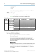
The Auto Power Down Cycles parameter on the Controller Settings tab allows you
to specify a range between 1 to 65,535 idle controller clock cycles. The counter for the
programmable time-out starts when there are no user read or write requests in the
command queue. Once the controller places the memory in power-down mode, it
responds by asserting the acknowledge signal,
local_powerdown_ack
.
1 HPC II supports only precharge power-down mode and not active power-down
mode.
Configuration and Status Register (CSR) Interface
The configuration and status register interface is a 32-bit wide interface that uses the
Avalon-MM interface standard. The CSR interface allows you to configure the timing
parameters, address widths, and the behavior of the controller for without leveling
interfaces. If you do not need this feature, you can disable it and all the programmable
settings are fixed to the values configured during the generation process. This
interface is synchronous to the controller clock.
1 The CSR interface is not fully supported for DDR3 SDRAM with leveling interfaces,
such as DIMMs.
f Refer to Table 7–9 through Table 7–23 in page 7–18 for detailed information about the
register maps.
Error Correction Coding (ECC)
The optional ECC logic comprises an encoder and a decoder-corrector, which can
detect and correct single-bit errors, and detect double-bit errors. The ECC logic is
available in two widths: 64/72 bit and 32/40 bit. The ECC logic has the following
features:
■ Hamming code ECC logic that encodes every 64 or 32 bits of data into 72 or 40 bits
of codeword.