External Memory Interface Handbook Volume 3 Section II. DDR3 SDRAM Controller with ALTMEMPHY IP User Guide External Memory Interface Handbook Volume 3 Section II. DDR3 SDRAM Controller with ALTMEMPHY IP User Guide 101 Innovation Drive San Jose, CA 95134 www.altera.com EMI_DDR3_UG-2.1 Document last updated for Altera Complete Design Suite version: Document publication date: 10.
© 2010 Altera Corporation. All rights reserved. ALTERA, ARRIA, CYCLONE, HARDCOPY, MAX, MEGACORE, NIOS, QUARTUS and STRATIX are Reg. U.S. Pat. & Tm. Off. and/or trademarks of Altera Corporation in the U.S. and other countries. All other trademarks and service marks are the property of their respective holders as described at www.altera.com/common/legal.html.
Contents Chapter 1. About This IP Release Information . . . . . . . . . . . . . . . . . . . . . . . . . . . . . . . . . . . . . . . . . . . . . . . . . . . . . . . . . . . . . . . . . . . . . 1–2 Device Family Support . . . . . . . . . . . . . . . . . . . . . . . . . . . . . . . . . . . . . . . . . . . . . . . . . . . . . . . . . . . . . . . . . . . 1–2 Features . . . . . . . . . . . . . . . . . . . . . . . . . . . . . . . . . . . . . . . . . . . . . . . . . . . . . . . . . . . . . . . . . . . . . . . . .
iv Contents Step 3: Read Resynchronization (Capture) Clock Phase . . . . . . . . . . . . . . . . . . . . . . . . . . . . . . . . . . 5–5 Step 4: Read and Write Datapath Timing . . . . . . . . . . . . . . . . . . . . . . . . . . . . . . . . . . . . . . . . . . . . . . 5–5 Step 5: Address and Command Clock Cycle . . . . . . . . . . . . . . . . . . . . . . . . . . . . . . . . . . . . . . . . . . . . 5–5 Step 6: Postamble . . . . . . . . . . . . . . . . . . . . . . . . . . . . . . . . . . . . . . . . . . . .
Contents v Control Logic . . . . . . . . . . . . . . . . . . . . . . . . . . . . . . . . . . . . . . . . . . . . . . . . . . . . . . . . . . . . . . . . . . . . . . . . . 6–5 Error Correction Coding (ECC) . . . . . . . . . . . . . . . . . . . . . . . . . . . . . . . . . . . . . . . . . . . . . . . . . . . . . . . . . 6–5 Interrupts . . . . . . . . . . . . . . . . . . . . . . . . . . . . . . . . . . . . . . . . . . . . . . . . . . . . . . . . . . . . . . . . . . . . . . . . . 6–8 Partial Writes . . . . . .
vi Contents Half-Rate Read (Non Burst-Aligned Address) . . . . . . . . . . . . . . . . . . . . . . . . . . . . . . . . . . . . . . . . . . . 9–18 Half-Rate Write (Non Burst-Aligned Address) . . . . . . . . . . . . . . . . . . . . . . . . . . . . . . . . . . . . . . . . . . . 9–20 Half-Rate Read With Gaps . . . . . . . . . . . . . . . . . . . . . . . . . . . . . . . . . . . . . . . . . . . . . . . . . . . . . . . . . . . . 9–22 Half-Rate Write With Gaps . . . . . . . . . . . . . . . . . . . . . . . . . . .
1. About This IP The Altera® DDR3 SDRAM Controller with ALTMEMPHY IP provides simplified interfaces to industry-standard DDR3 SDRAM. The ALTMEMPHY megafunction is an interface between a memory controller and the memory devices, and performs read and write operations to the memory. The DDR3 SDRAM Controller with ALTMEMPHY IP works in conjunction with the Altera ALTMEMPHY megafunction. The DDR3 SDRAM Controller with ALTMEMPHY IP and ALTMEMPHY megafunction support DDR3 SDRAM interfaces in half-rate mode.
1–2 Chapter 1: About This IP Release Information The ALTMEMPHY megafunction creates the datapath between the memory device and the memory controller. The megafunction is available as a stand-alone product or can be used in conjunction with Altera high-performance memory controllers. When using the ALTMEMPHY megafunction as a stand-alone product, use with either custom or third-party controllers.
Chapter 1: About This IP Features 1–3 Table 1–2 shows the level of support offered by the DDR3 SDRAM Controller with ALTMEMPHY IP to each of the Altera device families. Table 1–2.
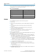
1–4 Chapter 1: About This IP Features ■ No support for data-mask (DM) pins for ×4 DDR3 SDRAM DIMMs or components, so select No for Drive DM pins from FPGA when using ×4 devices. ■ The ALTMEMPHY megafunction supports half-rate DDR3 SDRAM interfaces only. In addition, Table 1–3 shows the features provided by the DDR3 SDRAM HPC and HPC II. Table 1–3.
Chapter 1: About This IP Unsupported Features 1–5 Table 1–3. DDR3 SDRAM HPC and HPC II Features (Part 2 of 2) Controller Architecture Features IP functional simulation models for use in Altera-supported VHDL and Verilog HDL simulator HPC HPC II v v Notes to Table 1–3: (1) HPC II supports additive latency values greater or equal to tRCD-1, in clock cycle unit (tCK). (2) This feature is not supported with DDR3 SDRAM with leveling.
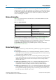
1–6 Chapter 1: About This IP Resource Utilization Table 1–4. Resource Utilization in Arria II GX Devices Memory Type DDR3 SDRAM (without leveling) PHY Rate Half (Note 1) Memory Width (Bits) Combinational ALUTS Logic Registers M9K Blocks Memory ALUTs 8 1,431 1,189 2 18 16 1,481 1,264 4 2 64 1,797 1,970 12 22 72 1,874 2,038 13 2 Note to Table 1–4: (1) The listed resource utilization refers to resources used by the ALTMEMPHY megafunction with AFI only.
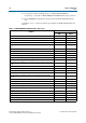
Chapter 1: About This IP Resource Utilization 1–7 High-Performance Controller Table 1–6 and Table 1–7 show the typical sizes for the DDR3 SDRAM HPC (including ALTMEMPHY) for Stratix III and Stratix IV devices. Table 1–6. Resource Utilization in Stratix III Devices Local Data Width (Bits) Memory Width (Bits) Combinational ALUTs Dedicated Logic Registers Memory (M9K) 32 8 1,891 1,558 2 64 16 1,966 1,707 3 256 64 2,349 2,591 9 288 72 2,442 2,739 10 Table 1–7.
1–8 Chapter 1: About This IP System Requirements Table 1–10.
Chapter 1: About This IP Installation and Licensing 1–9 Free Evaluation Altera's OpenCore Plus evaluation feature is only applicable to the DDR3 SDRAM HPC. With the OpenCore Plus evaluation feature, you can perform the following actions: ■ Simulate the behavior of a megafunction (Altera MegaCore function or AMPPSM megafunction) within your system. ■ Verify the functionality of your design, as well as evaluate its size and speed quickly and easily.
1–10 External Memory Interface Handbook Volume 3 Section II.
2. Getting Started Design Flow You can implement the DDR3 SDRAM Controller with ALTMEMPHY IP using either one of the following flows: ■ SOPC Builder flow ■ MegaWizard Plug-In Manager flow You can only instantiate the ALTMEMPHY megafunction using the MegaWizard Plug-In Manager flow. Figure 2–1 shows the stages for creating a system in the Quartus II software using either one of the flows. Figure 2–1.
2–2 Chapter 2: Getting Started SOPC Builder Flow The SOPC Builder flow offers the following advantages: ■ Generates simulation environment ■ Creates custom components and integrates them via the component wizard ■ Interconnects all components with the Avalon-MM interface The MegaWizard Plug-In Manager flow offers the following advantages: ■ Allows you to design directly from the DDR3 SDRAM interface to peripheral device or devices ■ Achieves higher-frequency operation SOPC Builder Flow The SOPC
Chapter 2: Getting Started SOPC Builder Flow 2–3 6. Click Finish to complete parameterizing the DDR3 SDRAM Controller with ALTMEMPHY IP and add it to the system. Completing the SOPC Builder System To complete the SOPC Builder system, perform the following steps: 1. In the System Contents tab, select Nios II Processor and click Add. 2. On the Nios II Processor page, in the Core Nios II tab, select altmemddr for Reset Vector and Exception Vector. 3.
2–4 Chapter 2: Getting Started MegaWizard Plug-In Manager Flow 8. For this example system, ensure all the other modules are clocked on the altmemddr_sysclk, to avoid any unnecessary clock-domain crossing logic. 9. Click Generate. 1 Among the files generated by SOPC Builder is the Quartus II IP File (.qip). This file contains information about a generated IP core or system. In most cases, the .
Chapter 2: Getting Started MegaWizard Plug-In Manager Flow 2–5 c Use the simulation models only for simulation and not for synthesis or any other purposes. Using these models for synthesis creates a nonfunctional design. 1 Some third-party synthesis tools can use a netlist that contains only the structure of the MegaCore function, but not detailed logic, to optimize performance of the design that contains the MegaCore function. If your synthesis tool supports this feature, turn on Generate netlist.
2–6 Chapter 2: Getting Started Generated Files Generated Files Table 2–2 shows the ALTMEMPHY generated files. Table 2–2. ALTMEMPHY Generated Files (Part 1 of 2) File Name Description alt_mem_phy_defines.v Contains constants used in the interface. This file is always in Verilog HDL regardless of the language you chose in the MegaWizard Plug-In Manager. .html Lists the top-level files created and ports used in the megafunction. .
Chapter 2: Getting Started Generated Files 2–7 Table 2–2. ALTMEMPHY Generated Files (Part 2 of 2) File Name Description _alt_mem_phy.v Contains all modules of the ALTMEMPHY variation except for the sequencer. This file is always in Verilog HDL language regardless of the language you chose in the MegaWizard Plug-In Manager. The DDR3 SDRAM sequencer is included in the _alt_mem_phy_seq.vhd file. _bb.v/.
2–8 Chapter 2: Getting Started Generated Files Table 2–3. Modules in _alt_mem_phy.v File (Part 2 of 2) Module Name Usage Description _alt_mem_phy_re ad_dp_group DDR3 SDRAM ALTMEMPHY variations (Stratix III and Stratix IV devices only) A per DQS group version of _alt_mem_phy_read_dp. _alt_mem_phy_rd ata_valid DDR3 SDRAM ALTMEMPHY variations Generates read data valid signal to sequencer and controller.
Chapter 2: Getting Started Generated Files 2–9 Table 2–5. Controller Generated Files—DDR3 High-Performance Controller (HPC) Filename Description _auk_ddr_hp_controller_wrapper.vo or .vho VHDL or Verilog HDL IP functional simulation model. _auk_ddr_hp_controller_ecc_ wrapper.vo or .vho ECC functional simulation model. . Table 2–6.
2–10 Chapter 2: Getting Started HardCopy Device Migration Guidelines HardCopy Device Migration Guidelines In HardCopy III and HardCopy IV designs where higher core performance is required and I/O performance is not a limiting factor, you can prototype your HardCopy design in a faster speed grade companion FPGA. However, this practice introduces some restrictions and limitations.
Chapter 2: Getting Started HardCopy Device Migration Guidelines 2–11 Table 2–7. PHY Sequencer Parameters (Part 2 of 2) Parameter 1 Setting PLL_STEPS_PER_CYCLE 40 MEM_IF_ADDR_CMD_PHASE 240 The sequencer in this example is set up to operate with 40 PLL phase steps per clock cycle. (This information appears in the message panel of the ALTMEMPHY parameter editor during generation of the IP core.
2–12 Chapter 2: Getting Started HardCopy Device Migration Guidelines As shown in Table 2–9, the Quartus II Fitter restricts the VCO operating range to 1212.1 MHz, rather than the 1515 MHz of Table 2–8. This restriction produces a phase step mismatch between the PLL generated by the Quartus II Fitter and the PHY sequencer setup written in the RTL.
3. Parameter Settings ALTMEMPHY Parameter Settings The Parameter Settings page in the ALTMEMPHY parameter editor (Figure 3–1) allows you to parameterize the following settings: ■ Memory Settings ■ PHY Settings ■ Board Settings Figure 3–1. ALTMEMPHY Parameter Settings Page The text window at the bottom of the MegaWizard Plug-In Manager displays information about the memory interface, warnings, and errors if you are trying to create something that is not supported.
3–2 Chapter 3: Parameter Settings ALTMEMPHY Parameter Settings The following sections describe the four tabs of the Parameter Settings page in more detail. Memory Settings In the Memory Settings tab, you can select a particular memory device for your system and choose the frequency of operation for the device. Under General Settings, you can choose the device family, speed grade, and clock information.
Chapter 3: Parameter Settings ALTMEMPHY Parameter Settings 3–3 Table 3–2 describes the options available to filter the Memory Presets that are displayed. This set of options is where you indicate whether you are creating a datapath for DDR3 SDRAM. Table 3–2. Memory Presets List Parameter Name Description Memory type You can filter the type of memory to display, for example, DDR3 SDRAM. Memory vendor You can filter the memory types by vendor.
3–4 Chapter 3: Parameter Settings ALTMEMPHY Parameter Settings Figure 3–2 shows the Preset Editor dialog box for a DDR3 SDRAM. Figure 3–2. DDR3 SDRAM Preset Editor The Advanced option is only available for Arria II GX and Stratix IV devices. This option shows the percentage of memory specification that is calibrated by the FPGA. The percentage values are estimated by Altera based on the process variation. External Memory Interface Handbook Volume 3 Section II.
Chapter 3: Parameter Settings ALTMEMPHY Parameter Settings 3–5 Table 3–3 through Table 3–5 describe the DDR3 SDRAM parameters available for memory attributes, initialization options, and timing parameters. Table 3–3. DDR3 SDRAM Attributes Settings (Part 1 of 2) Parameter Name Output clock pairs from FPGA Range (1) 1–6 Units Description pairs Defines the number of differential clock pairs driven from the FPGA to the memory.
3–6 Chapter 3: Parameter Settings ALTMEMPHY Parameter Settings Table 3–3. DDR3 SDRAM Attributes Settings (Part 2 of 2) Parameter Name Range (1) Units Description Row address width 12–16 bits Defines the number of row address bits for your interface. If your DDR3 SDRAM device’s row address bus is 12-bit wide, set the row address width to 13 and set the 13th bit to logic-level low (or leave the 13th bit unconnected to the memory device) in the top-level file.
Chapter 3: Parameter Settings ALTMEMPHY Parameter Settings 3–7 Table 3–4. DDR3 SDRAM Initialization Options (Part 2 of 3) Parameter Name Enable the DLL in the memory devices ODT Rtt nominal value Dynamic ODT (Rtt_WR) value Range Yes or No ODT disable, RZQ/4, RZQ/2, RZQ/6 Dynamic ODT off, RZQ/4, RZQ/2 Units Description — Enables the DLL in the memory device when set to Yes.
3–8 Chapter 3: Parameter Settings ALTMEMPHY Parameter Settings Table 3–4. DDR3 SDRAM Initialization Options (Part 3 of 3) Parameter Name Memory auto self refresh method Memory self refresh range Range Units Description — Sets the auto self-refresh method for the memory device. The DDR3 SDRAM Controller with ALTMEMPHY IP currently does not support the ASR option that you need for extended temperature memory self-refresh. — Determines the temperature range for self refresh.
Chapter 3: Parameter Settings ALTMEMPHY Parameter Settings 3–9 Table 3–5. DDR3 SDRAM Timing Parameter Settings (Part 2 of 3) Parameter Name Range (Note 1) Units Description tWTR 1–6 tCK Minimum write-to-read command delay. The controller waits for this period of time after the end of a write command before issuing a subsequent read command to the same bank. This timing parameter is specified in clock cycles and the value is rounded off to the next integer. tAC 0–750 ps DQ output access time.
3–10 Chapter 3: Parameter Settings ALTMEMPHY Parameter Settings Table 3–5. DDR3 SDRAM Timing Parameter Settings (Part 3 of 3) Parameter Name Range (Note 1) Units Description tRRD 2.06–64 ns The activate to activate time, per device, RAS to RAS delay timing parameter. tFAW 7.69–256 ns The four-activate window time, per device. tRTP 2.06–64 ns Read to precharge time. Note to Table 3–5: (1) See the memory device data sheet for the parameter range.
Chapter 3: Parameter Settings ALTMEMPHY Parameter Settings 3–11 The VREF referenced setup and hold signals for a rising edge are: tDS (VREF) = Base tDS + delta tDS + (VIH(ac) – VREF)/slew_rate = 25 + 0 + 175 = 200 ps tDH (VREF) = Base tDH + delta tDH + (VIH(dc) – VREF)/slew_rate = 100 + 0 + 100 = 200 ps If the output slew rate of the write data is different from 1V/ns, you have to first derate the tDS and tDH values, then translate these AC/DC level specs to VREF specification.
3–12 Chapter 3: Parameter Settings ALTMEMPHY Parameter Settings Table 3–6. ALTMEMPHY PHY Settings (Part 2 of 2) Parameter Name Instantiate DLL externally Applicable Device Families All supported device families. Enable dynamic parallel on-chip termination Stratix III and Stratix IV (OCT) Description Use this option with Stratix III, Stratix IV, HardCopy III, or HardCopy IV devices, if you want to apply a non-standard phase shift to the DQS capture clock.
Chapter 3: Parameter Settings DDR3 SDRAM Controller with ALTMEMPHY Parameter Settings 3–13 Board Settings Click Next or the Board Settings tab to set the options described in Table 3–7. The board settings parameters are set to model the board level effects in the timing analysis. The options are available if you choose Arria II GX or Stratix IV device for your interface. Otherwise, the options are disabled. Table 3–7.
3–14 Chapter 3: Parameter Settings DDR3 SDRAM Controller with ALTMEMPHY Parameter Settings The Memory Settings, PHY Settings, and Board Settings tabs provide the same options as in the ALTMEMPHY Parameter Settings page. Figure 3–3. DDR3 SDRAM Controller with ALTMEMPHY Settings Controller Settings Table 3–8 shows the options provided on the Controller Settings tab. External Memory Interface Handbook Volume 3 Section II.
Chapter 3: Parameter Settings DDR3 SDRAM Controller with ALTMEMPHY Parameter Settings 3–15 Table 3–8. Controller Settings (Part 1 of 3) Parameter Controller architecture Controller Architecture — Description Specifies the controller architecture. Enable self-refresh controls Both Turn on to enable the controller to allow you to have control on when to place the external memory device in self-refresh mode, refer to “User-Controlled Self-Refresh Logic” on page 7–8 (HPC II).
3–16 Chapter 3: Parameter Settings DDR3 SDRAM Controller with ALTMEMPHY Parameter Settings Table 3–8. Controller Settings (Part 2 of 3) Parameter Controller Architecture Description Local maximum burst count HPC II Specifies a burst count to configure the maximum Avalon burst count that the controller slave port accepts. Controller latency HPC II Specifies a latency for the controller.
Chapter 3: Parameter Settings DDR3 SDRAM Controller with ALTMEMPHY Parameter Settings 3–17 Table 3–8. Controller Settings (Part 3 of 3) Parameter Multiple controller clock sharing Local interface protocol Controller Architecture Description Both This option is only available in SOPC Builder Flow. Turn on to allow one controller to use the Avalon clock from another controller in the system that has a compatible PLL.
3–18 External Memory Interface Handbook Volume 3 Section II.
4. Compiling and Simulating After setting the parameters for the MegaCore function, you can now integrate the MegaCore function variation into your design, and compile and simulate your design. The following sections detail the steps you need to perform to compile and simulate your design. Compiling the Design Figure 4–1 shows the top-level view of the Altera high-performance controller design as an example of how your final design looks after you integrate the controller and the user logic. Figure 4–1.
4–2 Chapter 4: Compiling and Simulating Compiling the Design 2. You can either use the _pin_assignments.tcl or the .ppf file to apply the I/O assignments generated by the MegaWizard Plug-In Manager. Using the .ppf file and the Pin Planner gives you the extra flexibility to add a prefix to your memory interface pin names. You can edit the assignments either in the Assignment Editor or Pin Planner.
Chapter 4: Compiling and Simulating Compiling the Design ■ 4–3 Alternatively, to change the pin names that do not match the design, you can add a prefix to your pin names by performing the following steps: a. On the Assignments menu, click Pin Planner. b. On the Edit menu, click Create/Import Megafunction. c. Select Import an existing custom megafunction and navigate to .ppf. d. Type the prefix you want to use in Instance name. For example, change mem_addr to core1_mem_addr. 3.
4–4 Chapter 4: Compiling and Simulating Simulating the Design 6. Select your required I/O driver strength (derived from your board simulation) to ensure that you correctly drive each signal or ODT setting and do not suffer from overshoot or undershoot. 7. To compile the design, on the Processing menu, click Start Compilation. After you have compiled the example top-level file, you can perform RTL simulation or program your targeted Altera device to verify the example top-level file in hardware.
Chapter 4: Compiling and Simulating Simulating the Design ■ 4–5 Full calibration—across all pins and chip selects. This option allows for longer simulation time. Available for ×4 and ×8 DDR3 SDRAM between 300 MHz and 533 MHz. You cannot use the wizard-generated memory model, if you select Full Calibration. You must use a memory-vendor provided memory model that supports write leveling calibration.
4–6 External Memory Interface Handbook Volume 3 Section II.
5. Functional Description—ALTMEMPHY The ALTMEMPHY megafunction creates the datapath between the memory device and the memory controller, and user logic in various Altera devices. The ALTMEMPHY megafunction GUI helps you configure multiple variations of a memory interface. You can then connect the ALTMEMPHY megafunction variation with either a user-designed controller or with an Altera high-performance controller.
5–2 Chapter 5: Functional Description—ALTMEMPHY Block Description Block Description Figure 5–1 on page 5–2 shows the major blocks of the ALTMEMPHY megafunction and how it interfaces with the external memory device and the controller. The ALTPLL megafunction is instantiated inside the ALTMEMPHY megafunction, so that you do not need to generate the clock to any of the ALTMEMPHY blocks. Figure 5–1.
Chapter 5: Functional Description—ALTMEMPHY Block Description 5–3 The major advantage of the ALTMEMPHY megafunction is that it supports an initial calibration sequence to remove process variations in both the Altera device and the memory device. In Arria series and Stratix series devices, the DDR3 SDRAM ALTMEMPHY calibration process centers the resynchronization clock phase into the middle of the captured data valid window to maximize the resynchronization setup and hold margin.
5–4 Chapter 5: Functional Description—ALTMEMPHY Block Description Figure 5–2 shows the calibration flow. Figure 5–2. Calibration Flow—Without Leveling Memory Device and PHY Initialization Write Training Patterns Read Resynchronization Clock Phase Read and Write Datapath Timing Address and Command Clock Cycle Postamble Prepare for User Mode VT Tracking User Mode Step 1: Memory Device Initialization This step initializes the memory device according to the DDR3 SDRAM specification.
Chapter 5: Functional Description—ALTMEMPHY Block Description ■ 5–5 Mixed: ‘b0011 - DDIO high and low bits have to toggle Loading a mixed pattern is complex, because write latency is unknown at this time. Two sets of write and read operations (single pin resynchronization (capture) clock phase sweeps, (“Step 3: Read Resynchronization (Capture) Clock Phase”) are required to accurately write the mixed pattern to memory. 1 Memory bank 0, row 0, and column addresses 0 to 55 store calibration data.
5–6 Chapter 5: Functional Description—ALTMEMPHY Block Description When the data calibration phase is completed, the sequencer issues the mimic calibration sequence every 128 ms. During initial calibration, the mimic path is sampled using the measure clock (measure_clk has a _1x or _2x suffix, depending whether the ALTMEMPHY is a full-rate or half-rate design). The sampled value is then stored by the sequencer.
Chapter 5: Functional Description—ALTMEMPHY Block Description 1 5–7 The mimic path in Arria II GX, Stratix III and Stratix IV devices is similar to Figure 5–3. The only difference is that the mem_clk[0] pin is generated by DDIO register; mem_clk_n[0] is generated by signal splitter. Figure 5–3.
5–8 Chapter 5: Functional Description—ALTMEMPHY Block Description ■ Banks 0, 1, and 2 ■ Row 0 ■ All columns Bank 0 is written to for the block training pattern and clock cycle calibration (DQ_1T and AC_1T). Bank 1 is written to for write deskew (DQ). Bank 2 is written to for write deskew (DM). For each bank, only row 0 is accessed. The number of columns accessed can vary, but you should avoid writing to all columns in these banks and row 0.
Chapter 5: Functional Description—ALTMEMPHY Block Description 5–9 Figure 5–5 shows the calibration flow. Figure 5–5.
5–10 Chapter 5: Functional Description—ALTMEMPHY Block Description 1 On multiple rank DDR3 SDRAM DIMMs, address signals are routed differently to each rank (referred to in the JEDEC specification as address mirroring). Ranks with address mirroring can be specified in the memory Preset Editor in the Mirror addressing field. 1 RTL simulation of address mirroring is not currently supported by the memory model generated with the example testbench.
Chapter 5: Functional Description—ALTMEMPHY Block Description 5–11 Step 7: Write Clock Path Setup After the sequencer has the optimum settings for read capture and resynchronization setup, the sequencer calibrates the write datapath by configuring the alignment registers in the IOE and the DQ and DQS phase shift per DQS group.
5–12 Chapter 5: Functional Description—ALTMEMPHY Block Description Figure 5–6 shows a 1T chip select signal (mem_cs_n), which is active low, and disables the command in the memory device. All commands are masked when the chip-select signal is inactive. The mem_cs_n signal is considered part of the command code. Figure 5–6.
Chapter 5: Functional Description—ALTMEMPHY Block Description 5–13 Stratix III and Stratix IV Devices The address and command clock is one of the PLL dedicated clock outputs whose phase can be adjusted to meet the setup and hold requirements of the memory clock. The Stratix III address and command clock, ac_clk_1x, is half rate. The command and address pins use the DDIO output circuitry to launch commands from either the rising or falling edges of the clock.
5–14 Chapter 5: Functional Description—ALTMEMPHY Block Description The input clock to the PLL does not have any other fan-out to the PHY, so you do not have to use a global clock resource for the path between the clock input pin to the PLL. You must use the PLL located in the same device quadrant or side as the memory interface and the corresponding clock input pin for that PLL, to ensure optimal performance and accurate timing results from the Quartus II software.
Chapter 5: Functional Description—ALTMEMPHY Block Description 5–15 Table 5–1. DDR3 SDRAM Clocking in Arria II GX Devices (Part 2 of 2) Clock Name (1) Postscale Counter Phase (Degrees) Clock Rate Clock Network Type Notes Address and command clock. C3 ac_clk_2x –90° Full-Rate Global The ac_clk_2x clock is derived from either mem_clk_2x (when you choose 0° or 180° phase shift) or write_clk_2x (when you choose 90° or 270° phase shift).
5–16 Chapter 5: Functional Description—ALTMEMPHY Block Description Table 5–2 shows the PLL outputs and their usage for Stratix III and Stratix IV devices. Table 5–2.
Chapter 5: Functional Description—ALTMEMPHY Block Description 5–17 Table 5–2. DDR3 SDRAM Clocking Stratix IV and Stratix III Devices (Part 2 of 2) Postscale Counter Clock Name (1) Set in the GUI C6 ac_clk_1x Phase (Degrees) Clock Rate Half-Rate Clock Network Type Notes Regional Address and command clock. Notes to Table 5–2: (1) In full-rate designs a _1x clock may run at full-rate clock rate. (2) This clock should be of the same clock network clock as the resync_clk_1x clock.
5–18 Chapter 5: Functional Description—ALTMEMPHY Block Description Figure 5–8.
Chapter 5: Functional Description—ALTMEMPHY Block Description 5–19 Figure 5–9 shows the order of the functions performed by the read datapath and the frequency at which the read data is handled. Figure 5–9.
5–20 Chapter 5: Functional Description—ALTMEMPHY Block Description Read Data Alignment Data alignment is the process controlled by the sequencer to ensure the correct captured read data is present in the same half-rate clock cycle at the output of the read data DPRAM. Data alignment is implemented using memory blocks in the core of devices. Postamble Protection A dedicated postamble register controls the gating of the shifted DQS signal that clocks the DQ input registers at the end of a read operation.
Chapter 5: Functional Description—ALTMEMPHY Block Description 5–21 Figure 5–10 shows the order of the functions performed by the read datapath and the frequency at which the read data is handled. Figure 5–10.
5–22 Chapter 5: Functional Description—ALTMEMPHY Block Description The postamble path is also calibrated to determine the correct clock cycle, clock phase shift, and delay chain settings. You can see the process in simulation if you choose Full calibration (long simulation time) mode in the MegaWizard Plug-In Manager. Write Datapath This topic discusses the write datapath. Arria II GX Devices The write datapath logic efficiently transfers data from the HDR memory controller to DDR3 SDRAM.
Chapter 5: Functional Description—ALTMEMPHY ALTMEMPHY Signals 5–23 Figure 5–12 shows the reordered or the reordered-and-delayed HDR data is then converted to DDR data within the IOE element using both the half-rate and full-rate clocks. Figure 5–12.
5–24 Chapter 5: Functional Description—ALTMEMPHY ALTMEMPHY Signals 1 Signals with the prefix mem_ connect the PHY with the memory device; ports with the prefix ctl_ connect the PHY with the controller.
Chapter 5: Functional Description—ALTMEMPHY ALTMEMPHY Signals 5–25 Table 5–3. Interface to the DDR3 SDRAM Devices (Note 1) Signal Name mem_err_out_n (4) Type Width (2) Input Description The signal sent from the DIMM to the PHY to indicate that a parity error has occured for a particular cycle. 1 Notes to Table 5–3: (1) Connected to I/O pads. (2) Refer to Table 5–6 for parameter description. (3) Output is for memory device, and input path is fed back to ALTMEMPHY megafunction for VT tracking.
5–26 Chapter 5: Functional Description—ALTMEMPHY ALTMEMPHY Signals Table 5–4. AFI Signals (Part 2 of 3) Signal Name aux_scan_clk aux_scan_clk_reset_n Type Output Output Width (1) Description 1 Low frequency scan clock supplied primarily to clock any user logic that interfaces to the PLL and DLL reconfiguration interfaces.
Chapter 5: Functional Description—ALTMEMPHY ALTMEMPHY Signals 5–27 Table 5–4. AFI Signals (Part 3 of 3) Signal Name Type Width (1) Output ctl_rdata_valid Output ctl_rlat Description DWIDTH_RATIO/2 Read data valid indicating valid read data on ctl_rdata. This signal is two-bits wide (as only half-rate or DWIDTH_RATIO = 4 is supported) to allow controllers to issue reads and writes that are aligned to either the half-cycle of the half-rate clock.
5–28 Chapter 5: Functional Description—ALTMEMPHY ALTMEMPHY Signals Table 5–5. Other Interface Signals (Part 2 of 4) Signal Name Width Description Input DQS_DELA Y_CTL_WI DTH Allows the use of DLL in another ALTMEMPHY instance in this ALTMEMPHY instance. Connect the dqs_delay_ctrl_export port on the ALTMEMPHY instance with a DLL to the dqs_delay_ctrl_import port on the other ALTMEMPHY instance.
Chapter 5: Functional Description—ALTMEMPHY ALTMEMPHY Signals 5–29 Table 5–5. Other Interface Signals (Part 3 of 4) Signal Name Type Width Description hc_scan_enable_ access Input 1 This signal switches the control of the levelling delay chains from the sequencer to the hc_scan_ signals. It should normally be tied low. hc_scan_enable_dq Input MEM_IF_ DWIDTH When hc_scan_enable_access is asserted, this bus directly connects to the ena inputs on the IO_CONFIG atoms for every DQ pin.
5–30 Chapter 5: Functional Description—ALTMEMPHY ALTMEMPHY Signals Table 5–5. Other Interface Signals (Part 4 of 4) Signal Name Type Width Description rsu_read_latency Output — The rsu_read_latency output is then set to the read latency (in phy_clk cycles) using the rsu_codvw_phase resynchronization clock phase. If calibration is unsuccessful then this signal is undefined.
Chapter 5: Functional Description—ALTMEMPHY PHY-to-Controller Interfaces 5–31 PHY-to-Controller Interfaces The following section describes the typical modules that are connected to the ALTMEMPHY variation and the port name prefixes each module uses. This section also describes using a custom controller. This section describes the AFI.
5–32 Chapter 5: Functional Description—ALTMEMPHY PHY-to-Controller Interfaces For half-rate designs, the AFI allows the controller to issue reads and writes that are aligned to either half-cycle of the half-rate phy_clk, which means that the datapaths can support multiple data alignments—word-unaligned and word-aligned writes and reads. Figure 5–15 and Figure 5–16 display the half-rate write operation. Figure 5–15.
Chapter 5: Functional Description—ALTMEMPHY PHY-to-Controller Interfaces ■ With the AFI, high and low signals are combined in one signal, so for a single chip select (ctl_cs_n) interface, ctl_cs_n[1:0], where location 0 appears on the memory bus on one mem_clk cycle and location 1 on the next mem_clk cycle.
5–34 Chapter 5: Functional Description—ALTMEMPHY PHY-to-Controller Interfaces Figure 5–17.
Chapter 5: Functional Description—ALTMEMPHY PHY-to-Controller Interfaces 5–35 Figure 5–18.
5–36 Chapter 5: Functional Description—ALTMEMPHY PHY-to-Controller Interfaces Figure 5–19 and Figure 5–20 show spaced word-unaligned writes and reads. Figure 5–19.
Chapter 5: Functional Description—ALTMEMPHY PHY-to-Controller Interfaces 5–37 Figure 5–20.
5–38 Chapter 5: Functional Description—ALTMEMPHY Using a Custom Controller Using a Custom Controller The ALTMEMPHY megafunction can be integrated with your own controller. This section describes the interface requirement and the handshake mechanism for efficient read and write transactions. Preliminary Steps Perform the following steps to generate the ALTMEMPHY megafunction: 1.
Chapter 5: Functional Description—ALTMEMPHY Using a Custom Controller 5–39 Calibration Process Requirements When the global reset_n is released the ALTMEMPHY handles the initialization and calibration sequence automatically. The sequencer calibrates memory interfaces by issuing reads to multiple ranks of DDR3 SDRAM (multiple chip select). Timing margins decrease as the number of ranks increases.
5–40 Chapter 5: Functional Description—ALTMEMPHY Using a Custom Controller The ALTMEMPHY provides a signal, ctl_rdata_valid, to indicate that the data on read data bus is valid. The width of this signal varies between half-rate and full-rate designs to support the option to indicate that the read data is not word aligned. Figure 5–21 and Figure 5–22 show these relationships. Figure 5–21.
Chapter 5: Functional Description—ALTMEMPHY Using a Custom Controller 5–41 The ctl_wlat signal is only valid when the calibration has been successfully completed by the ALTMEMPHY sequencer and does not change at any point during normal user mode operation. Figure 5–23 shows the operation of ctl_wlat port. Figure 5–23.
5–42 External Memory Interface Handbook Volume 3 Section II.
6. Functional Description— High-Performance Controller The high-performance controller (HPC) architecture instantiates encrypted control logic and the ALTMEMPHY megafunction. The controller accepts read and write requests from the user on its local interface, using either the Avalon-MM interface protocol or the native interface protocol. It converts these requests into the necessary SDRAM commands, including any required bank management commands.
6–2 Chapter 6: Functional Description—High-Performance Controller Block Description Figure 6–2 shows a block diagram of the DDR3 SDRAM HPC architecture. Figure 6–2.
Chapter 6: Functional Description—High-Performance Controller Block Description 6–3 Write Data Tracking Logic The write data tracking logic keeps track of the number of write data beats in the FIFO buffer. In native interface mode, this logic manages how much more data to request from the user logic and issues the local_wdata_req signal.
6–4 Chapter 6: Functional Description—High-Performance Controller Block Description PHY Interface Logic When the main state machine issues a write command to the memory, the write data for that write burst has to be fetched from the write data FIFO buffer. The relationship between write command and write data depends on the memory type, ALTMEMPHY interface type, CAS latency, and the full-rate or half-rate setting.
Chapter 6: Functional Description—High-Performance Controller Block Description 6–5 Control Logic Bus commands control SDRAM devices using combinations of the mem_ras_n, mem_cas_n, and mem_we_n signals. For example, on a clock cycle where all three signals are high, the associated command is a no operation (NOP). A NOP command is also indicated when the chip select signal is not asserted. Table 6–2 shows the standard SDRAM bus commands. Table 6–2.
6–6 Chapter 6: Functional Description—High-Performance Controller Block Description ■ Latency: ■ Maximum of 1 or 2 clock delay during writes ■ Minimum 1 or 3 clock delay during reads ■ Detects and corrects all single-bit errors. Also the ECC logic sends an interrupt when the user-defined threshold for a single-bit error is reached. ■ Detects all double-bit errors.
Chapter 6: Functional Description—High-Performance Controller Block Description ■ 6–7 The ECC controller—controls multiple encoder and decoder-correctors, so that the ECC can handle different bus widths.
6–8 Chapter 6: Functional Description—High-Performance Controller Block Description Interrupts The ECC logic issues an interrupt signal when one of the following scenarios occurs: ■ The single-bit error counter reaches the set maximum single-bit error threshold value. ■ The double-bit error counter reaches the set maximum double-bit error threshold value. The error counters increment every time the respective event occurs for all N parts of the return data word.
Chapter 6: Functional Description—High-Performance Controller Block Description 6–9 Figure 6–4 shows the partial write operation for HPC. The half-rate DDR3 SDRAM HPC supports a local size of 1 and 2. Figure 6–4. Partial Write for HPC 1 0 local_address 2 local_size X1 local_be local_wdata XF 89ABCDEF 01234567 mem_dm 67 mem_dq R R R EF CD AB 89 Note to Figure 6–4: (1) R represents the internal read-back memory data during the read-modify-write process.
6–10 Chapter 6: Functional Description—High-Performance Controller Block Description Table 6–3 shows the relationship between burst lengths and rate. Table 6–3. Burst Lengths and Rates Local Burst Length Rate Memory Burst Length 1 Half 4 2 Full 4 Local Burst Length 2 For a local burst length of 2, the write latency increases by two clock cycles; the read latency increases by one clock cycle (including checking and correction).
Chapter 6: Functional Description—High-Performance Controller Block Description 6–11 Table 6–4. ECC Registers (Part 2 of 3) Name Last or first double-bit error error address Last single-bit error error data Last single-bit error syndrome Last double-bit error error data Address 06 07 08 09 Size (Bits) 32 32 32 32 Attribute RO RO RO RO Default Description 00000000 This status register stores the last double-bit error error address. It can be cleared using the control word clear.
6–12 Chapter 6: Functional Description—High-Performance Controller Block Description Table 6–4. ECC Registers (Part 3 of 3) Name Address Single-bit error location status register 0C Double-bit error location status register 0D Size (Bits) Attribute 32 R/W 32 R/W Default Description 00000000 This status register stores the occurrence of single-bit error for each 64-bit part of the data word in every bit (refer to Table 6–8).
Chapter 6: Functional Description—High-Performance Controller Block Description 6–13 Table 6–6 shows the interrupt status register. Table 6–6. Interrupt Status Register Bit Name Description 0 Single-bit error When 1, single-bit error occurred. 1 Double-bit error When 1, double-bit error occurred. 2 Maximum single-bit error When 1, single-bit error maximum threshold exceeded. 3 Maximum double-bit error When 1, double-bit error maximum threshold exceeded.
6–14 Chapter 6: Functional Description—High-Performance Controller Example Top-Level File Table 6–9 shows the double-bit error location status register. Table 6–9. Double-Bit Error Location Status Register Bit Name Description Bits N-1 down to 0 Cause of Interrupt When 0, no double-bit error; when 1, double-bit error occurred in this 64-bit part. Others Reserved Reserved.
Chapter 6: Functional Description—High-Performance Controller Example Top-Level File 6–15 There are two Altera-generated memory models available—associative-array memory model and full-array memory model. The associative-array memory model (_mem model.v) allocates reduced set of memory addresses with a default depth of 2,048 or 2K address spaces.
6–16 Chapter 6: Functional Description—High-Performance Controller Top-level Signals Description ■ Address pin operation The example driver generates a series of write and read requests starting with an all-zeros pattern, a walking-one pattern, a walking-zero pattern, and ending with an all-zeros pattern. This test checks to make sure that all the individual address bits are operating correctly. You can skip this test by setting the test_addr_pin_on signal to logic zero.
Chapter 6: Functional Description—High-Performance Controller Top-level Signals Description 6–17 Table 6–12. Clock and Reset Signals (Part 2 of 2) Name Direction Description oct_ctl_rs_value Input ALTMEMPHY signal that specifies the serial termination value. Should be connected to the ALT_OCT megafunction output seriesterminationcontrol. oct_ctl_rt_value Input ALTMEMPHY signal that specifies the parallel termination value.
6–18 Chapter 6: Functional Description—High-Performance Controller Top-level Signals Description Table 6–13. Local Interface Signals (Part 2 of 4) Signal Name Direction Description Avalon burst begin strobe, which indicates the beginning of an Avalon burst. This signal is only available when the local interface is an Avalon-MM interface and the memory burst length is greater than 2. Unlike all other Avalon-MM signals, the burst begin signal does not stay asserted if local_ready is deasserted.
Chapter 6: Functional Description—High-Performance Controller Top-level Signals Description 6–19 Table 6–13. Local Interface Signals (Part 3 of 4) Signal Name local_powerdn_req local_self_rfsh_req Direction Description Input User control of the power-down feature.
6–20 Chapter 6: Functional Description—High-Performance Controller Top-level Signals Description Table 6–13. Local Interface Signals (Part 4 of 4) Signal Name Direction Description Output Read data valid signal. The local_rdata_valid signal indicates that valid data is present on the read data bus. The timing of local_rdata_valid is automatically adjusted to cope with your choice of resynchronization and pipelining options.
Chapter 6: Functional Description—High-Performance Controller Top-level Signals Description 6–21 Table 6–15 shows the ECC logic signals. Table 6–15. ECC Logic Signals Signal Name December 2010 Direction Description ecc_addr[] Input Address for ECC logic. ecc_be[] Input ECC logic byte enable. ecc_read_req Input Read request for ECC logic. ecc_wdata[] Input ECC logic write data. ecc_write_req Input Write request for ECC logic. ecc_interrupt Output Interrupt from ECC logic.
6–22 External Memory Interface Handbook Volume 3 Section II.
7. Functional Description— High-Performance Controller II The high-performance controller II (HPC II) architecture is an upgraded controller with higher efficiency and more features than the HPC. HPC II is recommended for all new designs. HPC II is pin-out compatible with your existing DDR high-performance designs.
7–2 Chapter 7: Functional Description—High-Performance Controller II Block Description ■ The side-band signals differ slightly for HPC II. If you use these signals, you need to perform the following steps. local_refresh_req ■ You need to drive an additional active high signal, local_refresh_chip, to control which chip to issue the user-refresh to. local_powerdn_req ■ The user-manual power signal is no longer supported in HPC II.
Chapter 7: Functional Description—High-Performance Controller II Block Description 7–3 Figure 7–2 shows a block diagram of the DDR3 SDRAM HPC II architecture. Figure 7–2.
7–4 Chapter 7: Functional Description—High-Performance Controller II Block Description ■ For single chip select: width = row bits + bank bits + column – 2 For every Avalon transaction, the number of read or write requests cannot exceed the the maximum local burst count of 64. Altera recommends that you set this maximum burst count to match your system master's supported burst count.
Chapter 7: Functional Description—High-Performance Controller II Block Description 7–5 Timer Logic The timer logic models the internal behavior of each bank in the memory interface and provides status output signals to the state machine. The state machine then decides whether to issue the look-ahead bank management command based on the timer status signals.
7–6 Chapter 7: Functional Description—High-Performance Controller II Block Description ■ afi_wdata_valid ■ afi_wdata ■ afi_dm During read, the afi_doing_read signal generates the afi_rdata_valid signal and controls the ALTMEMPHY postamble circuit. ODT Generation Logic The ODT generation logic generates the necessary ODT signals for DDR3 SDRAM HPC II memory devices, based on the scheme recommended by Altera. Table 7–1 shows which ODT signal on the adjacent DIMM is enabled. Table 7–1.
Chapter 7: Functional Description—High-Performance Controller II Block Description 7–7 Low-Power Mode Logic There are two types of low-power mode logic: the user-controlled self-refresh logic and automatic power-down with programmable time-out logic. User-Controlled Self-Refresh Logic When you assert the local_self_rfsh_req signal, the controller completes all pending reads and writes before it places the memory into self-refresh mode.
7–8 Chapter 7: Functional Description—High-Performance Controller II Block Description ■ A latency increase of one clock for both writes and reads. ■ Detects and corrects all single-bit errors. ■ Detects all double-bit errors. ■ Counts the number of single-bit and double-bit errors. ■ Accepts partial writes, which trigger a read-modify-write cycle, for memory devices with DM pins. ■ Is able to inject single-bit and double-bit errors to trigger ECC correction for testing and debugging purposes.
Chapter 7: Functional Description—High-Performance Controller II Block Description 7–9 1. The ECC logic sends a read command to the partial write address. 2. Upon receiving a return data from the memory for the particular address, the ECC logic decodes the data, checks for errors, and then merges the corrected or correct dataword with the incoming information. 3. The ECC logic issues a write to write back the updated data and the new ECC code.
7–10 Chapter 7: Functional Description—High-Performance Controller II Example Top-Level File Example Top-Level File The MegaWizard Plug-In Manager helps you create an example top-level file that shows you how to instantiate and connect the DDR3 SDRAM HPC II. The example top-level file consists of the DDR3 SDRAM HPC II, some driver logic to issue read and write requests to the controller, a PLL to create the necessary clocks, and a DLL (Stratix series only).
Chapter 7: Functional Description—High-Performance Controller II Example Top-Level File 7–11 Both the memory models display similar behaviors and have the same calibration time. 1 The memory model, _test_component.v/vhd, used in SOPC Builder designs, is actually a variation of the full-array memory model. To ensure your simulation works in SOPC Builder, use memory model with less than 512-Mbit capacity.
7–12 Chapter 7: Functional Description—High-Performance Controller II Top-level Signals Description ■ Low-power mode operation The example driver requests the controller to place the memory into power-down and self-refresh states, and hold it in those states for the amount of time specified by the COUNTER_VALUE signal. You can vary this value to adjust the duration the memory is kept in the low-power states. This test is only available if your controller variation enables the low-power mode option.
Chapter 7: Functional Description—High-Performance Controller II Top-level Signals Description 7–13 Table 7–4. Clock and Reset Signals (Part 2 of 2) Name Direction Description Output An alternative clock that the ALTMEMPHY megafunction provides to the user. This clock always runs at the same frequency as the external memory interface. In half-rate mode, this clock is twice the frequency of the phy_clk and can be used whenever a 2x clock is required.
7–14 Chapter 7: Functional Description—High-Performance Controller II Top-level Signals Description Table 7–5 shows the DD3 SDRAM HPC II local interface signals. Table 7–5. Local Interface Signals (Part 1 of 3) Signal Name Direction Description Memory address at which the burst should start. By default, the local address is mapped to the bank interleaving scheme. You can change the ordering via the Local-to-Memory Address Mapping option in the Controller Settings page.
Chapter 7: Functional Description—High-Performance Controller II Top-level Signals Description 7–15 Table 7–5. Local Interface Signals (Part 2 of 3) Signal Name local_read_req local_refresh_req local_refresh_chip Direction Description Input Read request signal. You cannot assert the read request signal before the reset_phy_clk_n signal goes high. Input User-controlled refresh request.
7–16 Chapter 7: Functional Description—High-Performance Controller II Top-level Signals Description Table 7–5. Local Interface Signals (Part 3 of 3) Signal Name local_rdata[] Direction Description Output Read data bus. The width of local_rdata is twice that of the memory data bus for a full rate controller; four times the memory data bus for a half rate controller. Output local_rdata_error Asserted if the current read data has an error.
Chapter 7: Functional Description—High-Performance Controller II Top-level Signals Description 7–17 Table 7–6. CSR Interface Signals (Part 2 of 2) (Part 2 of 2) Signal Name csr_rdata_valid csr_waitrequest Direction Description Output Read data valid signal. The csr_rdata_valid signal indicates that valid data is present on the read data bus. Output The csr_waitrequest signal indicates that the HPC II is busy and not ready to accept request signals.
7–18 Chapter 7: Functional Description—High-Performance Controller II Register Maps Description Table 7–8 shows the ALTMEMPHY Debug interface signals, which are located in _phy.v/vhd file. Table 7–8.
Chapter 7: Functional Description—High-Performance Controller II Register Maps Description 7–19 ALTMEMPHY Register Map The ALTMEMPHY register map allows you to control the memory components’ mode register settings. To access the ALTMEMPHY register map, connect the ALTMEMPHY Debug interface signals in Table 7–8 using the Avalon-MM protocol.
7–20 Chapter 7: Functional Description—High-Performance Controller II Register Maps Description Table 7–10. Address 0x005 Mode Register 0-1 (Part 2 of 2) Bit Default Access RTT 0 RW RTT/WL/OCD 0 RW 26 DQS# 0 RW 27 TDQS/RDQS 0 RW 28 QOFF 0 RW Reserved 0 — 22 25:23 31:29 Name Description Not used by the controller, but you can set and program into the memory device mode register. Reserved for future use. Table 7–11.
Chapter 7: Functional Description—High-Performance Controller II Register Maps Description 7–21 Controller Register Map The controller register map allows you to control the memory controller settings. To access the controller register map, connect the CSR interface signals in Table 7–6 using the Avalon-MM protocol. Table 7–12.
7–22 Chapter 7: Functional Description—High-Performance Controller II Register Maps Description Table 7–13. Address 0x110 Controller Status and Configuration Register (Part 2 of 2) Bit Name Default Access Description 17 SELF_RFSH 0 RW Setting this bit, or asserting the local_self_rfsh signal, causes the memory to go into self-refresh state. 18 SELF_RFSH-ACK 0 RO This bit indicates that the memory is in self-refresh state. 19 Reserved 0 — Reserved for future use.
Chapter 7: Functional Description—High-Performance Controller II Register Maps Description 7–23 Table 7–14. Address 0x120 Memory Address Size Register 0 Bit Name Default Access Description 7:0 Column address width — RW The number of column address bits for the memory devices in your memory interface. The range of legal values is 7-12. 15:8 Row address width — RW The number of row address bits for the memory devices in your memory interface. The range of legal values is 12-16.
7–24 Chapter 7: Functional Description—High-Performance Controller II Register Maps Description Table 7–17. Address 0x123 Memory Timing Parameters Register 0 Bit Name Default Access Description 3:0 tRCD — RW The activate to read or write a timing parameter. The range of legal values is 2-11 cycles. 7:4 tRRD — RW The activate to activate a timing parameter. The range of legal values is 2-8 cycles. 11:8 tRP — RW The precharge to activate a timing parameter.
Chapter 7: Functional Description—High-Performance Controller II Register Maps Description 7–25 Table 7–20. Address 0x126 Memory Timing Parameters Register 3 Bit 3:0 Name CAS latency, tCL Default Access Description — RW This value must be set to match the memory CAS latency. You must set this value in the 0x04 register map as well. 7:4 Additive latency, AL — RW Additive latency setting.
7–26 Chapter 7: Functional Description—High-Performance Controller II Register Maps Description Table 7–22. Address 0x131 ECC Status Register (Part 2 of 2) Bit Name Default Access Description 15:8 SBE_COUNT 0 RO Reports the number of single-bit errors that have occurred since the status register counters were last cleared. 23:16 DBE_COUNT 0 RO Reports the number of double-bit errors that have occurred since the status register counters were last cleared.
8. Latency Latency is defined using the local (user) side frequency and absolute time (ns). There are two types of latencies that exists while designing with memory controllers—read and write latencies, which have the following definitions: 1 ■ Read latency—the amount of time it takes for the read data to appear at the local interface after initiating the read request. ■ Write latency—the amount of time it takes for the write data to appear at the memory interface after initiating the write request.
8–2 Chapter 8: Latency Figure 8–1 shows a typical memory interface read latency path showing read latency from the time a local_read_req assertion is detected by the controller up to data available to be read from the dual-port RAM (DPRAM) module. Figure 8–1.
Chapter 8: Latency 8–3 You can separate the controller and ALTMEMPHY read data input latency into latency that occurred in the I/O element (IOE) and latency that occurred in the FPGA fabric. Table 8–2 shows the read and write latency derived from the write and read latency definitions for half rate controller for Stratix III and Stratix IV devices. 1 The exact latency depends on your precise configuration.
8–4 External Memory Interface Handbook Volume 3 Section II.
9. Timing Diagrams This chapter details the timing diagrams for the DDR3 SDRAM high-performance controllers (HPC) and high-performance controllers II (HPC II).
9–2 Chapter 9: Timing Diagrams DDR3 High-Performance Controllers Auto-Precharge The auto-precharge read and auto-precharge write commands allow you to indicate to the memory device that this read or write command is the last access to the currently open row. The memory device automatically closes (auto-precharges) the page it is currently accessing so that the next access to the same bank is quicker. This command is particularly useful for applications that require fast random accesses. Figure 9–1.
Chapter 9: Timing Diagrams DDR3 High-Performance Controllers 9–3 User Refresh Figure 9–2 shows the user refresh control interface. This feature allows you to control when the controller issues refreshes to the memory. This feature allows better control of worst case latency and allows refreshes to be issued in bursts to take advantage of idle periods. Figure 9–2.
9–4 External Memory Interface Handbook Volume 3 Section II. DDR3 SDRAM Controller with ALTMEMPHY IP User Guide Half-Rate Read for Avalon Interface Figure 9–3.
Chapter 9: Timing Diagrams DDR3 High-Performance Controllers 9–5 The following sequence corresponds with the numbered items in Figure 9–3: 1. The local read request signal is asserted. 2. The controller accepts the request, the local_ready signal is asserted. 3. The controller asserts the ctl_doing_rd to tell the PHY how many clock cycles of read data to expect. 4. The read command (RD) on the command bus. 5. The mem_dqs signal has the read data from the controller. 6.
9–6 External Memory Interface Handbook Volume 3 Section II. DDR3 SDRAM Controller with ALTMEMPHY IP User Guide Half-Rate Write for Avalon Interface Figure 9–4.
Chapter 9: Timing Diagrams DDR3 High-Performance Controllers 9–7 The following sequence corresponds with the numbered items in Figure 9–4: 1. The user logic requests write by asserting the local_write_req signal. 2. The local_ready signal is asserted, indicating that the controller has accepted the request. 3. The data written to the memory for the write command. 4. The write (WR) command on the command bus. 5. The valid write data on the ctl_wdata signal. 6.
9–8 External Memory Interface Handbook Volume 3 Section II. DDR3 SDRAM Controller with ALTMEMPHY IP User Guide Half Rate Write for Native Interface Figure 9–5.
Chapter 9: Timing Diagrams DDR3 High-Performance Controllers 9–9 The following sequence corresponds with the numbered items in Figure 9–5: 1. The user logic requests write by asserting the local_write_req signal. 2. The local_ready signal is asserted, indicating that the controller has accepted the request. 3. The data written to the memory for the write command. 4. The controller requests the user logic for the write data and byte-enables for the write by asserting the local_wdata_req signal. 5.
9–10 External Memory Interface Handbook Volume 3 Section II. DDR3 SDRAM Controller with ALTMEMPHY IP User Guide Initialization Timing Figure 9–6. Initialization Timing for HPC [1] [3] [2] [3] global_reset_n pll_locked phs_shft_busy seq_pll_select[3:0] seq_pll_start_reconfig seq_pll_inc_dec_n seq_ac_ras_n[1:0] seq_ac_cas_n[1:0] seq_ac_we_n[1:0] 3 3 3 memory_0_0.ck memory_0_0.ck_n memory_0_0.cke memory_0_0.cs_n memory_0_0.addr[13:0] memory_0_0.ras_n memory_0_0.cas_n memory_0_0.we_n memory_0_0.
Chapter 9: Timing Diagrams DDR3 High-Performance Controllers 9–11 The following sequence corresponds with the numbered items in Figure 9–6: 1. The PHY initialization stage; wait for PLL to unlock. 2. The DRAM initialization stage; reset sequence. 3. Various SDRAM bus commands during the initialization sequence. December 2010 Altera Corporation External Memory Interface Handbook Volume 3 Section II.
9–12 External Memory Interface Handbook Volume 3 Section II. DDR3 SDRAM Controller with ALTMEMPHY IP User Guide Calibration Timing Figure 9–7. Calibration Timing for HPC [1] [6] [4] [7] [8] [10] [9] [11] global_reset_n pll_locked phs_shft_busy seq_pll_select[3:0] seq_pll_start_reconfig seq_pll_inc_dec_n state[1:0] seq_ac_ras_n[1:0] seq_ac_cas_n[1:0] seq_ac_we_n[1:0] scan_enable_dq scan_enable_dqs mem_cas_n mem_ras_n mem_we_n memory_0_1.ba[0] memory_0_0.ck memory_0_0.ck_n memory_0_0.cke memory_0_0.
Chapter 9: Timing Diagrams DDR3 High-Performance Controllers II 9–13 The following sequence corresponds with the numbered items in Figure 9–7: 1. The write leveling stage. 2. The write leveling coarse phase sweep. 3. Fine T9/T10 delay chain sweep. 4. The write burst training pattern. 5. Three training patterns available at different addresses—zeroes, ones, and mixed. 6. The read path setup starts with the first operation, read deskew. 7. The read path deskew increases capture margin. 8.
9–14 External Memory Interface Handbook Volume 3 Section II. DDR3 SDRAM Controller with ALTMEMPHY IP User Guide Half-Rate Read (Burst-Aligned Address) Figure 9–8.
Chapter 9: Timing Diagrams DDR3 High-Performance Controllers II 9–15 The following sequence corresponds with the numbered items in Figure 9–8: 1. The user logic requests the first read by asserting the local_read_req signal, and the size and address for this read. In this example, the request is a burst of length of 2 to the local address 0×000000. This local address is mapped to the following memory address in half-rate mode: mem_row_address = 0×000000 mem_col_address = 0×0000 mem_bank_address = 0×00 2.
9–16 External Memory Interface Handbook Volume 3 Section II. DDR3 SDRAM Controller with ALTMEMPHY IP User Guide Half-Rate Write (Burst-Aligned Address) Figure 9–9.
Chapter 9: Timing Diagrams DDR3 High-Performance Controllers II 9–17 The following sequence corresponds with the numbered items in Figure 9–9: 1. The user logic asserts the first write request to row 0 so that row 0 is open before the next transaction. 2. The user logic asserts a second local_write_req signal with size of 2 and address of 0 (col = 0, row = 0, bank = 0, chip = 0).
9–18 External Memory Interface Handbook Volume 3 Section II. DDR3 SDRAM Controller with ALTMEMPHY IP User Guide Half-Rate Read (Non Burst-Aligned Address) Figure 9–10.
Chapter 9: Timing Diagrams DDR3 High-Performance Controllers II 9–19 The following sequence corresponds with the numbered items in Figure 9–10: 1. The user logic requests the first read by asserting the local_read_req signal, and the size and address for this read. In this example, the request is a burst of length of 2 to the local address 0×000001.
9–20 External Memory Interface Handbook Volume 3 Section II. DDR3 SDRAM Controller with ALTMEMPHY IP User Guide Half-Rate Write (Non Burst-Aligned Address) Figure 9–11.
Chapter 9: Timing Diagrams DDR3 High-Performance Controllers II 9–21 The following sequence corresponds with the numbered items in Figure 9–11: 1. The user logic asserts the first local_write_req signal with a size of 2 and an address of 0×000001. The local_ready signal is asserted along with the local_write_req signal, which indicates that the controller has accepted this request, and the user logic can request another read or write in the following clock cycle.
9–22 External Memory Interface Handbook Volume 3 Section II. DDR3 SDRAM Controller with ALTMEMPHY IP User Guide Half-Rate Read With Gaps Figure 9–12.
Chapter 9: Timing Diagrams DDR3 High-Performance Controllers II 9–23 The following sequence corresponds with the numbered items in Figure 9–12: 1. The user logic requests the first read by asserting the local_read_req signal, and the size and address for this read. In this example, the request is a burst of length of 2 to the local address 0×0000810.
9–24 Chapter 9: Timing Diagrams DDR3 High-Performance Controllers II The following sequence corresponds with the numbered items in Figure 9–13: 1. The user logic asserts a local_write_req signal with a size of 2 and an address of 0×0000F1C. 2. The controller issues the necessary memory command and address signals to the ALTMEMPHY megafunction for it to send to the memory device. 3.
Chapter 9: Timing Diagrams DDR3 High-Performance Controllers II 9–25 The following sequence corresponds with the numbered items in Figure 9–14: 1. The user logic asserts the first local_write_req signal with a size of 1 and an address of 0×000000. The local_ready signal is asserted along with the local_write_req signal, which indicates that the controller has accepted this request, and the user logic can request another read or write in the following clock cycle.
9–26 External Memory Interface Handbook Volume 3 Section II. DDR3 SDRAM Controller with ALTMEMPHY IP User Guide Write-Read-Write-Read Operation Figure 9–15.
Chapter 9: Timing Diagrams DDR3 High-Performance Controllers II 9–27 The following sequence corresponds with the numbered items in Figure 9–15: 1. The user logic requests the first write by asserting the local_write_req signal, and the size and address for this write. In this example, the request is a burst length of 1 to a local address 0x000002.
9–28 Chapter 9: Timing Diagrams DDR3 High-Performance Controllers II 13. The controller returns the first read data to the user by asserting the local_rdata_valid signal when there is valid read data on the local_rdata bus. If the ECC logic is disabled, there is no delay between the afi_rdata and the local_rdata buses. If there is ECC logic in the controller, there is one or three clock cycles of delay between the afi_rdata and local_rdata buses. External Memory Interface Handbook Volume 3 Section II.
Additional Information This chapter provides additional information about the document and Altera. Document Revision History The following table shows the revision history for this document. Date Version December 2010 2.1 July 2010 2.0 February 2010 1.3 February 2010 Changes Updated for 10.1. ■ Added information for new GUI parameters: Controller latency, Enable reduced bank tracking for area optimization, and Number of banks to track. ■ Removed information about IP Advisor.
Info–2 Chapter : Typographic Conventions Typographic Conventions The following table shows the typographic conventions this document uses. Visual Cue Meaning Bold Type with Initial Capital Letters Indicate command names, dialog box titles, dialog box options, and other GUI labels. For example, Save As dialog box. For GUI elements, capitalization matches the GUI.