
User guide
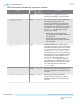

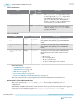
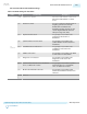
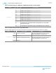
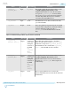

Table 2-48: Gearbox
Name Direction Clock
Domain
Description
rx_bitslip[<n>-1:0] Input
rx_clkout The rx_parallel_data slips 1 bit for every
positive edge of the rx_bitslip input. Keep
the minimum interval between rx_bitslip
pulses to at least 20 cycles. The maximum
shift is < pcswidth -1> bits, so that if the PCS
is 64 bits wide, you can shift 0-63 bits.
tx_enh_bitslip[<n>-1:0] Input rx_clkout
The value of this signal controls the number
of bits to slip the tx_parallel_data before
passing to the PMA.
Table 2-49: KR-FEC
Name Direction Clock Domain Description
tx_enh_frame[<n>-
1:0]
Output
tx_clkout
Asynchronous status flag output of TX KR-FEC
that signifies the beginning of generated KR FEC
frame
rx_enh_frame[<n>-
1:0]
Output rx_clkout Asynchronous status flag output of RX KR-FEC
that signifies the beginning of received KR FEC
frame
rx_enh_frame_diag_
status
Output rx_clkout
Asynchronous status flag output of RX KR-FEC
that indicates the status of the current received
frame.
• 00: No error
• 01: Correctable Error
• 10: Un-correctale error
• 11: Reset condition/pre-lock condition
Related Information
• ATX PLL IP Core on page 3-6
• CMU PLL IP Core on page 3-24
• fPLL IP Core on page 3-15
• Ports and Parameters on page 6-24
• Transceiver PHY Reset Controller Interfaces on page 4-13
This section describes the top-level signals for the Transceiver PHY Reset Controller IP core.
Enhanced PCS TX and RX Control Ports
This section describes the tx_control and rx_control bit encodings for different protocol
configurations.
When Enable simplified data interface is ON, all of the unused ports shown in the tables below, appear as
a separate port. For example: It appears as unused_tx_control/ unused_rx_control port.
2-62
Enhanced PCS TX and RX Control Ports
UG-01143
2015.05.11
Altera Corporation
Implementing Protocols in Arria 10 Transceivers
Send Feedback