
User guide

Follow these steps to request bus access:
1. Read the offset address 0x0.
2. Keep the value from MSB [7:2] and replace LSB [1:0] with 0x2.
3. Write the new value to offset address 0x0.
Follow these steps to return bus access to PreSICE:
1. Read offset address 0x0.
2. Keep the value from MSB [7:2] and replace LSB [1:0] with 0x3.
3. Write the new value to offset address 0x0.
Follow these steps to to enable the ATX PLL calibration enable bit:
1. Read the offset address 0x100.
2. Keep the value from MSB[7:1] and set LSB[0] to 1.
3. Write new value to offset address 0x100.
Enabling the fPLL, CDR/CMU PLL, and PMA calibration enable bits is similliar to enabling th ATX PLL.
Power-up Calibration
After device power-up, PreSICE automatically initiates the calibration process. The calibration process
can continue during device programming. The time required after device power-up to complete the
calibration process can vary by device. The total time taken can extend into the user-mode. The cal_busy
signals deassert to indicate the completion of the calibration process. You must ensure that the transceiver
reset sequence in your design waits for the calibration to complete before resetting the PLL and the
transceiver channel.
Initially, the cal_busy signal deasserts to indicate that power-up calibration is complete. If the
reconfig_waitrequest signal is still asserted, indicating that PreSICE controls the internal configuration
bus even after power-up calibration. You can request access whenever needed. Altera recommends that
you return the Avalon-MM interface back to PreSICE after you are done using it.
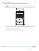
All power-up calibration starts from Vreg calibration for all banks and channels.
UG-01143
2015.05.11
Power-up Calibration
7-5
Calibration
Altera Corporation
Send Feedback