
User guide

a. Set ODI with DFE Enable to 1’b0 to use ODI with DFE disabled. Use ODI with DFE enabled will be
supported in future
b. Set Vertical Height to 6’h00 to select middle point in vertical
c. Set Horizontal Phase to 7’h71 to select horizontal phase 1
d. Set ODI Pattern Filter to 2’b00 to set pattern filter “0”
e. Refer to Start Pattern Checker on page 6-39 to see how many pattern errors are received
f. Set ODI Pattern Filter to 2’b01 to set pattern filter “1”
g. Repeat step to get pattern error information for pattern filter “1”
h. Add the error counters you get from step “2.e” and “2.g”, you can record if you get pattern error in
horizontal phase 1
i. Set Horizontal Phase to 7’h70 to select horizontal phase 2, repeat step “2.d” to “2.h” to record
pattern error information of horizontal phase 2
j. Similar as step “2.i”, further select horizontal phase 3, 4… until 128, record the corresponding
pattern error information
k. After you have pattern error information for all 128 horizontal phases, you can calculate the eye
center. For example, if you get pattern error free from horizontal phase 20 to 60, the eye center is
phase 40. In addition, the error free phase can roll over from phase 128 to phase 1, it is possible you
get error free from phase 1 to 10 and phase 98 to 128, then the eye center will be phase 118.
3. After eye center is located, the horizontal phase for one eye will be within +/-32 phases of the eye
center. The vertical height region is from 63 to 33, followed by 0 to 31. You can sweep the entire region
by repeating steps “2.e” through 2.h” to get pattern error information for one full eye.
Related Information
Arria 10 Transceiver Register Map
Start Pattern Checker
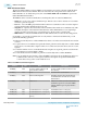
Start the pattern checker to see how many pattern errors have been received.
1. If you have checked “Enabled ODI acceleration logic” in the Dynamic Reconfiguration section of
Native PHY, then do the following steps:
a. Set ODI Accelerator Counter Reset to 1’b0, then set it to 1’b1 to reset the ODI Accelerator
Counters.
b. Set ODI Accelerator Counter Enable to 1’b1 to start the ODI Accelerator Counters.
c. Depending on your Bit Error Ratio requirement, wait for some time to let the ODI check for
pattern errors.
d. Set ODI Accelerator Counter Snapshot to 1’b1, then set it to 1’b0 to take a snapshot of the ODI
Accelerator Counters.
e. Read ODI Accelerator Error Counters to get error counters for pattern “0”.
2. If you did not check “Enabled ODI acceleration logic” in the Dynamic Reconfiguration page of Native
PHY, then do the following steps:
a. Set ODI Pattern Capture Reset to 1’b0, then set it to 1’b1 to reset the ODI pattern capture.
b. Set ODI Pattern Capture Start to 1’b1 to start the pattern capture.
c. Set Status Selection in address 0x144 to 6’h2D to select the ODI status bits in Status value.
d. Read Status value in address 0x177 to check the “Done” bit status. After it is asserted, go to the next
step.
UG-01143
2015.05.11
Start Pattern Checker
6-39
Reconfiguration Interface and Dynamic Reconfiguration
Altera Corporation
Send Feedback