
User guide
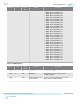
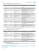
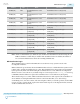

Address Bits Read /
Write
Feature Description
0x14C [5:0] RW Status Selection Select the status signals presented in Status
Value (address 0x177). The following
encodings are used by ODI:
• 6'h29: ODI Pattern Counter bits[7:0]
• 6'h2A: ODI Pattern Counter bits[15:8]
• 6'h2B: ODI Pattern Error bits[7:0]
• 6'h2C: ODI Pattern Error bits[15:8]
• 6'h2D: ODI Status bits
• Bit 0: Busy. When asserted, ODI is
collecting pattern counters and errors
• Bit 1: Done. When asserted, ODI has
finished the pattern counters and
errors collection
0x177
[7:0] R Status Value Status Value is defined by Status Selection in
address 0x14C
Related Information
• ODI Acceleration Logic on page 6-45
• Arria 10 PMA Architecture on page 5-1
Using ODI to Build On-chip Eye Process
You can use Arria 10 ODI to build an on-chip eye (EyeQ). The eye can be reported in a matrix with 64
horizontal steps and 63 vertical steps. Currently you can use EyeQ when the receiver doesn’t have DFE
enabled. Using EyeQ with a DFE enabled receiver channel will be supported later.
The phase interpolator in Arria 10 devices provides 128 horizontal steps across two UIs. However, the
horizontal step number does not have a fixed relationship with the incoming data eye. You must search
the eye center by sweeping all 128 horizontal steps. After the eye center is located, you only need to sweep
+/–32 steps of the eye center.
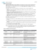
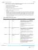
Refer to Arria 10 Transceiver Register Map and do the following steps to build your on-chip eye.
1. Enable ODI
a. Set ODI Enable to 2’b10 to enable ODI in CDR input node
b. Set ODI Vertical Scale based on hardware VCCER level
c. Select ODI Bandwidth based on incoming data rate
d. Set Reserved bits in address 0x144[6:3] to 4’b0001 for normal operation
e. Set ODI Data Processing Block Enable to 1’b1 to enable ODI data processing block
f. If DFE is enabled in receiver, set ODI with DFE Enable to 1’b1, otherwise set to 1’b0
g. Set ODI Pattern Counter Threshold to 3’b110. If required, you can set a lower number
h. Set Reserved bit in address 0x168[1] to 1’b1 for normal operation
i. Set Reserved bit in address 0x169[2] to 1’b1 for normal operation
2. Sweep horizontal steps from 1 to 128, recording pattern error status and locate the eye center
6-38
Using ODI to Build On-chip Eye Process
UG-01143
2015.05.11
Altera Corporation
Reconfiguration Interface and Dynamic Reconfiguration
Send Feedback