
User guide
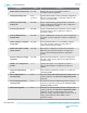
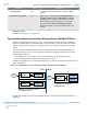
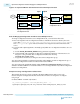
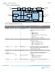
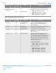
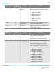
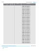
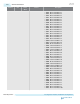

Figure 6-15: ODI Block Diagram
CTLE DFE CDR Deserializer
Deserializer
Phase
Interpolator
Deserializer
Bit Error
Ratio
Checker
ODI
Vref Generator ODI Sampler
Logic
Receiver
Input
Avalon-MM
Interface
To PCS/FPGA
Fabric
To Avalon-MM
Interface
Table 6-19: Register Map for ODI Circuitry
Address Bits Read /
Write
Feature Description
0x143 [1:0] RW Enable ODI These two bits are used to enable the eye
monitor. The following encodings are
defined:
• 2'b00 : Reserved
• 2'b01 : Reserved
• 2'b10 : Eye Monitor is enabled on CDR
input node
• 2'b11 : Eye Monitor is disabled
0x144 [1:0] RW ODI Vertical Scale Specify the vertical scale according to the
following encoding:
• 2'b01 : VCCR_GXB is 0.9 V
• 2'b10 : VCCR_GXB is 1.03 V
• 2'b11 : VCCR_GXB is 1.11 V
0x144 2 RW ODI Polarity Specifies the sign of the vertical height. When
0, the vertical height is negative. When 1, the
vertical height is positive.
0x144 3 RW Reserved Set to 1 for normal operation.
0x144 4
RW ODI Control Mode
Select Eye Monitor control mode {0x144[4],
0x145[6]} according to the following
encoding:
• 2'b00: Avalon-MM Register
• other values: Reserved
0x144 6
0x144 5 RW ODI Total Phase Step Set to 0 to select 128 horizontal phase steps
over 2 UI
6-32
On-Die Instrumentation
UG-01143
2015.05.11
Altera Corporation
Reconfiguration Interface and Dynamic Reconfiguration
Send Feedback