
User guide

For Native PHY 1—receive-only instance to be merged with Native PHY 0:
set_instance_assignment -name XCVR_RECONFIG_GROUP 0 -to
topdesign:topdesign_inst|<RX only instance name>*twentynm_hssi_avmm_if_inst*
Example 6-3: Using pin names
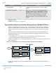
This example shows how to merge a transmit-only Native PHY instance with a receive-only
instance using pin names. These instances are assigned to reconfiguration group 1.
For Native PHY 0—transmit-only instance:
set_instance_assignment -name XCVR_RECONFIG_GROUP 1 -to
tx[0]
For Native PHY 1—receive-only instance to be merged with Native PHY 0:
set_instance_assignment -name XCVR_RECONFIG_GROUP 1 -to
rx[0]
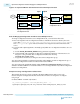
On-Die Instrumentation
ODI is used to analyze, diagnose, and verify high speed transceiver behavior and functions.
ODI determines the eye margin by using the phase interpolator, V
ref
generator, ODI sampler, and the Bit
Error Rate (BER) checker. The phase interpolator generates a sampling clock and the sampler examines
the data from the DFE output or receiver input pins. The BER checker compares the ODI sample with the
CDR sample to determine the BER. As the phase interpolator output clock phase is shifted by small
increments, the data error rate can increase or decrease. The number of steps of valid data is defined as
the width of the eye. If none of the steps yields valid data, the width of the eye is equal to 0, which means
the eye is closed.
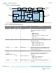
There are 64 horizontal steps and 127 (0 and –63 to +63 vertical steps) to monitor the eye margin. You
can set the vertical and horizontal addresses using the registers given in Table 6-21.
To enable ODI, you must enable the following three blocks:
• ODI Circuitry—Consists of V
ref
generator, ODI sampler and phase interpolator
• Adaptive blocks for the ODI—Consists of deserializer and Bit Error Rate checker
• ODI acceleration logic (optional)
UG-01143
2015.05.11
On-Die Instrumentation
6-31
Reconfiguration Interface and Dynamic Reconfiguration
Altera Corporation
Send Feedback