
User guide
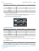
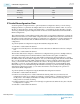
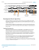
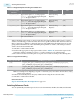

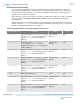
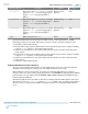
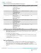
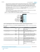
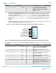

Table 6-8: Bit Values to Be Set
Address Bit Values
0x137[7] 1’b1
0x13C[7] 1’b0
0x132[5:4] 2’bxx
0x142[4] 1’b1
0x11D[0] 1’b1
Reverse Serial Loopback Mode (Post-CDR)
In the post-CDR mode, received data passes through the RX CDR and then loops back to the TX output
buffer. Perform read-modify-write to the following registers to enable this mode.
Figure 6-9: Reverse Serial Loopback Mode (Post-CDR)
PCS PMA
Serializer
PCS PMA
Transmitter
Receiver
Deserializer CDR
Post-CDR Reverse
Serial Loopback
Table 6-9: Bit Values to Be Set
Address Bit Values
0x137[7] 1’b0
0x13C[7] 1’b1
0x132[5:4] 2’b01
0x142[4] 1’b0
0x11D[0] 1’b0
Disabling Reverse Serial Loopback Mode (Pre-CDR and Post-CDR)
To disable reverse-serial loopback mode, set the address bits to the following values, by performing read-
modify-write.
Table 6-10: Bit Values to Be Set
Address Bit Values
0x137[7] 1’b0
UG-01143
2015.05.11
Enabling and Disabling Loopback Modes
6-17
Reconfiguration Interface and Dynamic Reconfiguration
Altera Corporation
Send Feedback