
User guide


Serial Loopback Mode
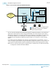
In serial loopback mode, a path exists between the serializer of the transmitter and the CDR of the
receiver, so that the data from the CDR is recovered from the serializer while the data from the receiver
serial input pin is ignored. You can enable or disable this mode.
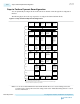
Figure 6-7: Serial Loopback Mode
PCS PMA
Serializer
PCS PMA
Deserializer
Transmitter
Receiver
CDR
Serial Loopback
To enable serial loopback mode:
1. Write 0x2 to address 0x0 of the channel
2. Perform a read-modify-write to address 0x2E1 to set bit 0 to 1’b1
3. Write 0x3 to address 0x0 of the channel
To disable serial loopback mode:
1. Write 0x2 to address 0x0 of the channel
2. Perform a read-modify-write to address 0x2E1 to set bit 0 to 1’b0
3. Write 0x3 to address 0x0 of the channel
You can also enable the serial loopback mode by turning on Enable rx_seriallpbken port in the Native
PHY IP Parameter Editor and driving the port to 1’b1.
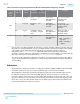
Reverse Serial Loopback Mode (Pre-CDR)
In the pre-CDR mode, data received through the RX input buffer is looped back to the TX output buffer.
You can enable the reverse serial loopback mode by performing read-modify-write to the following
registers.
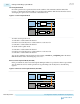
Figure 6-8: Reverse Serial Loopback Mode (Pre-CDR)
PCS PMA
Serializer
PCS PMA
Deserializer
Transmitter
Receiver
CDR
Pre-CDR Reverse
Serial Loopback
6-16
Enabling and Disabling Loopback Modes
UG-01143
2015.05.11
Altera Corporation
Reconfiguration Interface and Dynamic Reconfiguration
Send Feedback