
User guide


32'h00000000;
localparam HSSI_TX_PCS_PMA_INTERFACE_PLDIF_DATAWIDTH_MODE_ADDR_FIELD_VALUE = 1'h0;
The SystemVerilog configuration files contain two parts. The first part consists of a data array of 26-bit
hexadecimal values. The second part consists of parameter values. For the data array, each 26-bit hexadec‐
imal value is associated with a comment that describes the various bit positions.
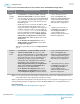
Table 6-2: Example of SystemVerilog Configuration File Line
Bit Position Description
[25:16] The channel or PLL address.
[15:8] The channel or PLL bit mask. The bit mask exposes the bits that are configured in either the
Transceiver Native PHY or the transmit PLL IP cores.
[7:0] Feature bit values.
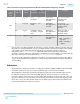
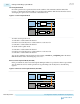
For example, a value of 26'h008FF04 represents an address of 0x008 and a bit mask of 0xFF. The four
features that reside at address 0x008 are:
• hssi_tx_pcs_pma_interface_pldif_datawidth_mode with a value of 1'h0
• hssi_tx_pcs_pma_interface_tx_pma_data_sel with a value of 2'h0
• hssi_tx_pcs_pma_interface_prbs_gen_pat with a value of 1'h0
• hssi_tx_pcs_pma_interface_sq_wave_num with a value of 4'h4
Writing to bit 7 of address 0x008 changes the hssi_tx_pcs_pma_interface_pldif_datawidth_mode
feature.
The MIF file and C header file are set up similarly to the SystemVerilog package file. Multiple transceiver
features may reside at the same address. Also, a single transceiver feature may span across multiple
addresses.
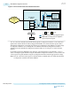
Dynamic reconfiguration requires at least two configurations of the Altera Transceiver Native PHY IP or
PLL. One configuration defines the base transceiver or PLL configuration and the other configurations
define the modified or target configurations. Use the IP Parameter Editor to create base and modified
configurations of the Transceiver Native PHY or PLL IP core, according to the following table.
UG-01143
2015.05.11
Configuration Files
6-7
Reconfiguration Interface and Dynamic Reconfiguration
Altera Corporation
Send Feedback