
User guide


Rate Match FIFO
In asynchronous systems, the upstream transmitter and local receiver can be clocked with independent
reference clocks. Frequency differences in the order of a few hundred PPM can corrupt the data when
latching from the recovered clock domain to the local receiver reference clock domain. The rate match
FIFO compensates for small clock frequency differences between these two clock domains by inserting or
removing SKP symbols in the data stream to keep the FIFO from going empty or full respectively.
The PCI-Express 3.0 base specification defines that the SKP Ordered Set (OS) can be 66, 98, 130, 162, or
194 bits long. The SKP OS has the following fixed bits: 2-bit Sync, 8-bit SKP END, and a 24-bit LFSR = 34
Bits. The Rate Match/Clock compensation block adds or deletes the 4 SKP characters (32-bit) to keep the
FIFO from going empty or full, respectively. If the FIFO is nearly full, it deletes the 4 SKP characters (32-
bit) by disabling write whenever a SKP is found. If the FIFO is nearly empty, the design waits for a SKP
Ordered Set to start and then stops reading the data from the FIFO, and inserts a SKP in the outgoing
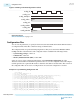
data. The actual FIFO core (memory element) is in the Shared Memory block in the PCS channel.
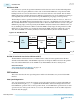
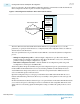
Figure 5-47: Rate Match FIFO
SKIP
Inserter
Asynchronous
FIFO
SKIP
Deleter
data_out data_in
rd_clk
wr_clk
fifo_pempty
rd_en
data
fifo_pfull
wr_en
data
RX FIFO (Shared with Standard and Enhanced PCS)
The RX FIFO in each channel ensures a reliable transfer of data and status signals between the PCS
channel and the FPGA fabric. The RX FIFO compensates for the phase difference between the parallel
PCS clock and the FPGA fabric clock. In PIPE mode, the RX FIFO works in low latency mode.
Related Information
Arria 10 Standard PCS Architecture on page 5-37
For more information about RX FIFO.
PIPE Interface
This section describes the Auto Speed Negotiation and the Clock Data Recovery Control of the PIPE
interface.
Auto Speed Negotiation
Auto speed negotiation controls the operating speed of the transceiver when operating under PIPE 3.0
modes. By monitoring the pipe_rate signal from the PHY-MAC, this feature changes the transceiver
from PIPE Gen1 operation mode to Gen2 operation mode, or from PIPE Gen1 operation mode to Gen2
operation mode to Gen3 operation mode, or vice versa. The PIPE interface clock rate will be adjusted to
match the data throughput.
5-56
Rate Match FIFO
UG-01143
2015.05.11
Altera Corporation
Arria 10 Transceiver PHY Architecture
Send Feedback