
User guide
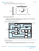
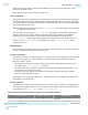
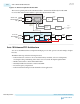
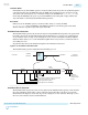
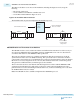
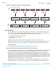

Figure 5-12: CDR Sample and ODI Sample to Calculate Bit Error Ratio
64 Steps
CDR
Sample
Horizontal
Offset
Vertical
Offset
ODI Sample
128 Steps
Clock Data Recovery (CDR) Unit
The PMA of each channel includes a channel PLL that you can configure as a receiver clock data recovery
(CDR) for the receiver. You can also configure the channel PLL of channels 1 and 4 as a clock multiplier
unit (CMU) PLL for the transmitter in the same bank.
Figure 5-13: Channel PLL Configured as CDR
Serial Clock
rx_is_lockedtoref
rx_serial_data
refclk
Recovered Clock
LTR/LTD
Controller
Phase
Detector
(PD)
Down
Up
Up
Down
Charge Pump
&
Loop Filter
Voltage
Controlled
Oscillator
(VCO)
Lock
Detect
Phase
Frequency
Detector
(PFD)
/2
Channel PLL
M
Divider
(1)
Note:
1. The Quartus II software automatically chooses the optimal values.
rx_is_lockedtodata
N
Divider
(1)
L
Divider
(1)
Lock-to-Reference Mode
In LTR mode, the phase frequency detector (PFD) in the CDR tracks the receiver input reference clock.
The PFD controls the charge pump that tunes the VCO in the CDR. The rx_is_lockedtoref status
5-14
Clock Data Recovery (CDR) Unit
UG-01143
2015.05.11
Altera Corporation
Arria 10 Transceiver PHY Architecture
Send Feedback