
User guide
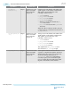
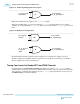
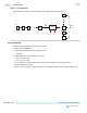
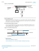

Figure 4-13: Physical Routing Delay Skew in Bonded Channels
PHY Reset
Controller
TX
Channel[ n - 1]
TX
Channel[1]
TX
Channel[0]
Bonded TX
Channels
tx_digitalreset
FPGA Fabric
You must provide a Synopsys Design Constraint (SDC) for the reset signals to guarantee that your design
meets timing requirements. The Quartus II software generates an .sdc file when you generate the
Transceiver Native PHY IP.
This .sdc contains basic false paths for most asynchronous signals, including resets. In the case of bonded
designs, this file contains examples for maximum skew on bonded designs. This .sdc file contains an
example false_path and an example max_skew constraint for the tx_digitalreset signals.
All modified IP constraints from a generated .sdc file must be moved to the project’s main .sdc file,
because changes will be lost if the IP is regenerated.
This skew is present whether you tie all tx_digitalresets together, or you control them separately. If
your design includes the Transceiver PHY Reset Controller IP core, you can substitute your instance and
interface names for the generic names shown in the example.
Example 4-1: SDC Constraint for TX Digital Reset When Bonded Clocks Are Used
set_max_skew -from *<IP_INSTANCE_NAME> *tx_digitalreset*r_reset
-to *pld_pcs_interface* <1/2 coreclk period in ps>
In the above example, you must make the following substitutions:
• <IP_INSTANCE_NAME>—substitute the name of your reset controller IP instance or PHY IP
instance
• <½ coreclk period in ps>—substitute half of the clock period of your design in picoseconds
If your design has custom reset logic, replace the *<IP_INSTANCE_NAME>*tx_digitalreset*r_reset
with the source register for the TX PCS reset signal, tx_digitalreset.
UG-01143
2015.05.11
Timing Constraints for Bonded PCS and PMA Channels
4-21
Resetting Transceiver Channels
Altera Corporation
Send Feedback