
User guide
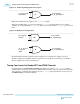
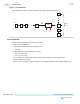

Configuration Combination ALUTs Logic Registers
Four transceiver channels,
shared TX reset, separate RX
resets
approximately 100 approximately 150
Using a User-Coded Reset Controller
You can design your own user-coded reset controller instead of using Altera's Transceiver PHY Reset
Controller IP core. Your user-coded reset controller must provide the following functionality for the
recommended reset sequence:
• A clock signal input for your reset logic
• Holds the transceiver channels in reset by asserting the appropriate reset control signals
• Checks the PLL status (for example, checks the status of pll_locked and pll_cal_busy)
Note: You must ensure a stable reference clock is present at the PLL transmitter before releasing PLL
powerdown (pll_powerdown).
User-Coded Reset Controller Signals
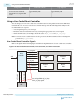
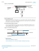
Refer to the signals in the following figure and table for implementation of a user-coded reset controller.
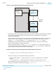
Figure 4-10: User-Coded Reset Controller, Transceiver PHY, and TX PLL Interaction
User-Coded
Reset
Controller
Transceiver PHY Instance
tx_analogreset
tx_digitalreset
rx_analogreset
rx_digitalreset
tx_cal_busy
rx_cal_busy
rx_is_lockedtoref
rx_is_lockedtodata
Transmit
PLL
pll_powerdown
pll_cal_busy
pll_locked
clock
You can logical OR the pll_cal_busy
and tx_cal_busy signals.
Receiver
PCS
Receiver
PMA
Transmitter
PCS
Transmitter
PMA
4-18
Using a User-Coded Reset Controller
UG-01143
2015.05.11
Altera Corporation
Resetting Transceiver Channels
Send Feedback