
User guide
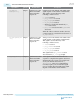

Signal Name Direction Clock Domain Description
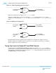
tx_digital-
reset[<n>-1:0]
Output Synchronous to the
Transceiver PHY
Reset Controller
input clock.
Digital reset for TX channels. The width of this
signal depends on the number of TX channels.
This signal is asserted when any of the
following conditions is true:
• reset is asserted
• pll_powerdown is asserted
• pll_cal_busy is asserted
• tx_cal_busy is asserted
• PLL has not reached the initial lock (pll_
locked deasserted)
• pll_locked is deasserted and tx_manual is
deasserted
When all of these conditions are false, the reset
counter begins its countdown for deassertion of
tx_digitalreset.
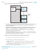
tx_analogreset[<n>
-1:0]
Output Synchronous to the
Transceiver PHY
Reset Controller
input clock.
Analog reset for TX channels. The width of this
signal depends on the number of TX channels.
This signal is asserted when any of the
following conditions is true:
• reset is asserted
• pll_powerdown is asserted
• pll_cal_busy is asserted
• tx_cal_busy is asserted
This signal follows pll_powerdown and is
deasserted after pll_locked goes high.
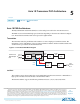
tx_ready[<n>-1:0]
Output Synchronous to the
Transceiver PHY
Reset Controller
input clock.
Status signal to indicate when the TX reset
sequence is complete. This signal is deasserted
while the TX reset is active. It is asserted a few
clock cycles after the deassertion of tx_
digitalreset. Some protocol implementa‐
tions may require you to monitor this signal
prior to sending data. The width of this signal
depends on the number of TX channels.
4-16
Transceiver PHY Reset Controller Interfaces
UG-01143
2015.05.11
Altera Corporation
Resetting Transceiver Channels
Send Feedback