
User guide

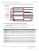
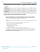
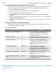

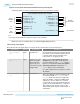
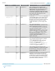

Figure 4-9: Transceiver PHY Reset Controller IP Core Top-Level Signals
Generating the IP core creates signals and ports based on your parameter settings.
pll_locked[<p>–1:0]
pll_select[<p*n>–1:0] (1)
tx_cal_busy[<n>–1:0]
rx_cal_busy[<n>–1:0]
rx_is_lockedtodata[<n>–1:0]
tx_manual[<n>–1:0]
rx_manual[<n>–1:0]
clock
reset
Transceiver PHY Reset Controller Top-Level Signals
tx_digitalreset[<n>–1:0]
tx_analogreset[<n>–1:0]
tx_ready[<n>–1:0]
rx_digitalreset[<n>–1:0]
rx_analogreset[<n>–1:0]
rx_ready[<n>–1:0]
pll_powerdown[<p>–1:0]
PLL and
Calibration
Status
PLL Powerdown
TX and RX
Resets and Status
Clock
and Reset
PLL
Control
Note:
(1) n=1 for pll_select signal width when a single TX reset sequence is used for all channels.
Note: PLL control is available when you enable the Expose Port parameter.
Table 4-5: Top-Level Signals
This table describes the signals in the above figure in the order that they are shown in the figure.
Signal Name Direction Clock Domain Description
pll_locked[<p>-
1:0]
Input Asynchronous Provides the PLL locked status input from each
PLL. When asserted, indicates that the TX PLL
is locked. When deasserted, the PLL is not
locked. There is one signal per PLL.
pll_select[<p*n>-
1:0]
Input Synchronous to the
Transceiver PHY
Reset Controller
input clock. Set to
zero when not using
multiple PLLs.
When you select Use separate TX reset per
channel, this bus provides enough inputs to
specify an index for each pll_locked signal to
listen to for each channel. When Use separate
TX reset per channel is disabled, the pll_
select signal is used for all channels.
n=1 when a single TX reset sequence is used for
all channels.
tx_cal_busy[<n> -
1:0]
Input Asynchronous
This is the calibration status signal that results
from the logical OR of pll_cal_busy and tx_
cal_busy signals. The signal goes high when
either the TX PLL or Transceiver PHY initial
calibration is active. It will not be asserted if
you manually re-trigger the calibration IP. The
signal goes low when calibration is completed.
This signal gates the TX reset sequence. The
width of this signals depends on the number of
TX channels.
4-14
Transceiver PHY Reset Controller Interfaces
UG-01143
2015.05.11
Altera Corporation
Resetting Transceiver Channels
Send Feedback