
User guide


Clock Data Recovery in Manual Lock Mode
Use the clock data recovery (CDR) manual lock mode to override the default CDR automatic lock mode
depending on your design requirements.
The two control signals to enable and control the CDR in manual lock mode are rx_set_locktoref and
rx_set_locktodata.
Related Information
"Transceiver PHY Reset Controller IP Core" chapter of the Altera Transceiver PHY IP Core User
Guide.
Refer to the description of the rx_digitalreset signal in the "Top-Level Signals" table for information
about using the manual lock mode.
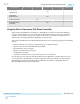
Control Settings for CDR Manual Lock Mode
Use the following control settings to set the CDR lock mode:
Table 4-2: Control Settings for the CDR in Manual Lock Mode
rx_set_locktoref rx_set_locktodata CDR Lock Mode
0 0 Automatic
1 0 Manual-RX CDR LTR
X 1 Manual-RX CDR LTD
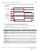
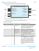
Resetting the Transceiver in CDR Manual Lock Mode
The numbers in this list correspond to the numbers in the following figure, which guides you through the
steps to put the CDR in manual lock mode.
1. Make sure that the calibration is complete (rx_cal_busy is low) and the transceiver goes through the
initial reset sequence. The rx_digitalreset and rx_analogreset signals should be low. The
rx_is_lockedtoref is a don't care and can be either high or low. The rx_is_lockedtodata and
rx_ready signals should be high, indicating that the transceiver is out of reset. Alternatively, you can
start directly with the CDR in manual lock mode after the calibration is complete.
2. Assert the rx_set_locktoref signal high to switch the CDR to the lock-to-reference mode. The
rx_is_lockedtodata status signal is deasserted. Assert the rx_digitalreset signal high at the same
time or after rx_set_lockedtoref is asserted if you use the user-coded reset. When the Transceiver
PHY reset controller is used, the rx_digitalreset is automatically asserted.
3. After the rx_digitalreset signal gets asserted, the rx_ready status signal is deasserted.
4. Assert the rx_set_locktodata signal high after t
LTR_LTD_manual
to switch the CDR to the lock-to-data
mode. The rx_is_lockedtodata status signal gets asserted, which indicates that the CDR is now set to
LTD mode. The rx_is_lockedtoref status signal can be a high or low and can be ignored.
5. Deassert the rx_digitalreset signal after t
LTD_Manual
.
6. If you are using the Transceiver PHY Reset Controller, the rx_ready status signal gets asserted after
the rx_digitalreset signal is deasserted. This indicates that the receiver is now ready to receive data
with the CDR in manual mode.
UG-01143
2015.05.11
Clock Data Recovery in Manual Lock Mode
4-7
Resetting Transceiver Channels
Altera Corporation
Send Feedback