
User guide

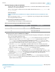
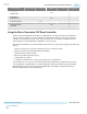
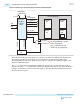

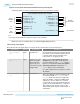
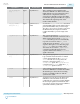

Figure 4-5: Receiver Reset Sequence Following Power-Up
Device Power Up
rx_cal_busy
rx_is_lockedtodata
rx_analogreset
rx_digitalreset
1
2
3
Device in User Mode
4
t
rx_analogreset
min 40 ns
t
LTD
min 4 μs
Note: rx_is_lockedtodata might toggle when there is no data at the receiver input.
rx_is_lockedtoref is a don't care when rx_is_lockedtodata is asserted. rx_analogreset must
always be followed by rx_digitalreset.
Resetting the Receiver During Device Operation
Follow this reset sequence to reset the analog or digital blocks of the receiver at any point during the
device operation. Use this reset to re-establish a link or after dynamic reconfiguration. The step numbers
correspond to the numbers in the following waveform.
1. Assert rx_analogreset and rx_digitalreset. Ensure that rx_cal_busy is low. You must reset the
PCS by asserting rx_digitalreset every time you assert rx_analogreset.
2. Deassert rx_analogreset after a minimum duration of two parallel system clock cycles.
3. Ensure rx_is_lockedtodata is asserted for t
LTD
before deasserting rx_digitalreset.
Figure 4-6: Receiver Reset Sequence During Device Operation
Device Power Up
rx_is_lockedtodata
rx_analogreset
rx_digitalreset
1
2
3
1
t
LTD
t
rx_analogreset
Minimum of two parallel system clock cycles
rx_cal_busy
Note:
rx_is_lockedtodata might toggle when there is no data at the receiver input.
rx_is_lockedtoref is a don't care when rx_is_lockedtodata is asserted.
4-6
Resetting the Receiver During Device Operation
UG-01143
2015.05.11
Altera Corporation
Resetting Transceiver Channels
Send Feedback